Honda CR-V: Shafts and Clutches
Mainshaft Disassembly, Inspection, and Reassembly
1. Inspect the thrust needle bearing and the needle bearing for galling and rough movement.
2. Inspect the splines for excessive wear and damage.
3. Check shaft bearing surface for scoring and excessive wear.
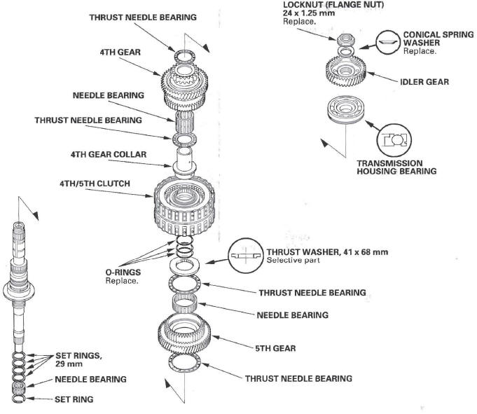
4. Before installing the O-rings, wrap the shaft splines with tape to prevent O-ring damage.
5. Lubricate all parts with ATF during assembly.
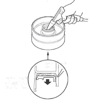
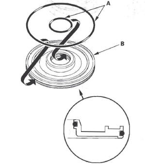
6. Install the conical spring washer, 41 x 68 mm thrust washer in the direction shown.
7. Replace the locknut and conical spring washer with new ones when assembling the transmission.
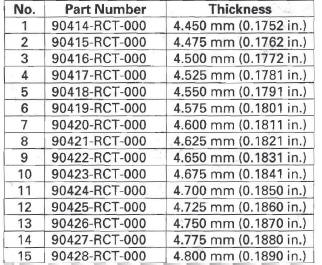
8. Check the 5th gear clearance.
Mainshaft 5th Gear Axial Clearance Inspection
1. Remove the mainshaft transmission housing bearing.
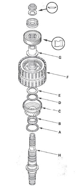
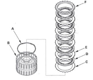
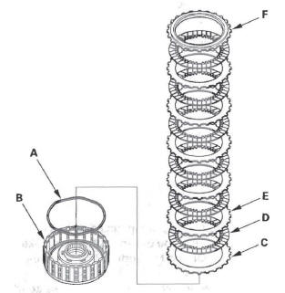
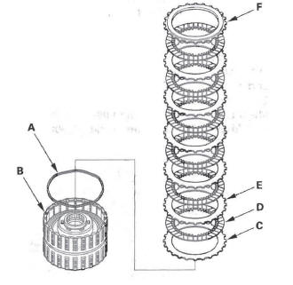
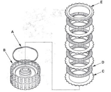
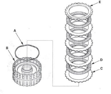
2. Install the thrust needle bearing (A), 5th gear (B), needle bearing (C), thrust needle bearing (D), 41 x 68 mm thrust washer (E), 4th/5th clutch (F), 4th gear collar (G), and transmission housing bearing (H) on the mainshaft (I). Do not install the O-rings during inspection.
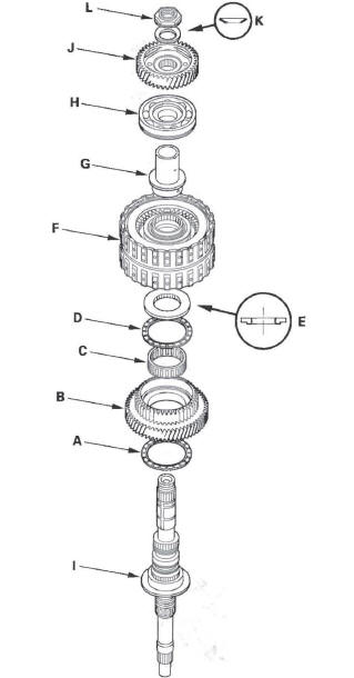
3. Install the idler gear (J) on the mainshaft by a press, then install the conical spring washer (K) and locknut (L).
4. Tighten the locknut to 29 N*m (3.0 kgf*m, 22 Ibf*ft).
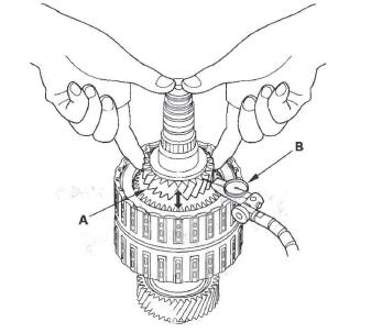
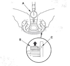
5. Set the dial indicator (A) on the 5th gear (B).
6. Lift the 5th gear (A) up while holding the mainshaft, and use the dial indicator (B) to read the 5th gear axial clearance.
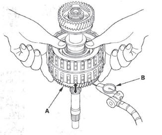
7. Measure the 5th gear axial clearance in at least three places while moving the 5th gear. Use the average as the actual clearance.
Standard: 0.04-0.10 mm (0.002-0.004 in.)
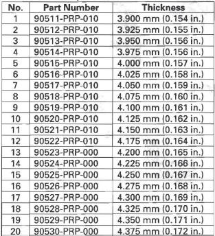
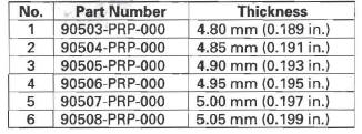
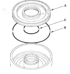
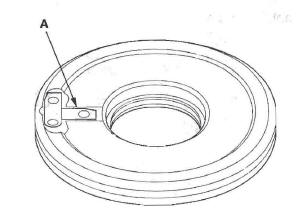
8. If the clearance is out of standard, remove the 41 x 68 mm thrust washer and measure its thickness (A).
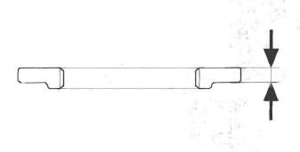
9. Select and install a new thrust washer, then recheck.
THRUST WASHER, 41 x 68 mm
10. After replacing the thrust washer, make sure the clearance is within the standard.
11. Disassemble the installed parts from the mains haft.
12. Reinstall the bearing in the transmission housing.
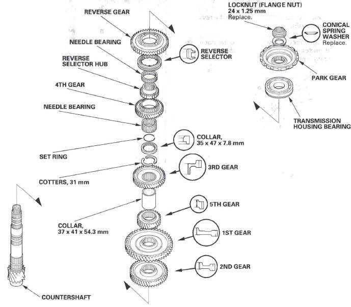
Countershaft Disassembly, Inspection, and Reassembly
1. Inspect the thrust needle bearing and the needle bearing for galling and rough movement.
2. Inspect the splines for excessive wear and damage.
3. Check shaft bearing surface for scoring and excessive wear.
4. Lubricate all parts with ATF during assembly.
5. Install the conical spring washer, reverse selector, 35 x 47 x 7.8 mm collar, and all gears in the direction shown.
6. Replace the locknut and conical spring washer with new ones when assembling the transmission. The countershaft locknut has left-hand threads.
7. Some reverse selector hubs, and the 3rd gear are press-fitted to the countershaft; special tools are needed to remove them and to install them.
Countershaft Reverse Selector Hub and 3rd Gear Removal
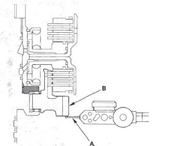
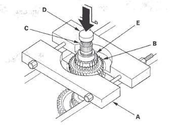
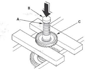
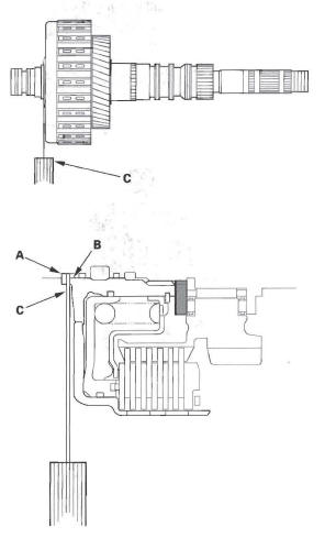
1. Install a commercially available bearing separator (A) on the 4th gear (B). Set a press on the countershaft (C) with a spacer (D) between the press and countershaft, and remove the reverse selector hub (E).
NOTE: Some reverse selector hubs are not press-fitted, and can be removed without using a bearing separator and a press.
2. Remove the needle bearing, set ring, 35 x 47 x 7.8 mm collar, and cotters.
3. Set the press on the countershaft (A) with a spacer (B) between the press and countershaft, and remove the 3rd gear (C).
4. Remove the 37 x 41 x 54.3 mm collar, 5th gear, 1st gear, and 2nd gear.
Countershaft 3rd Gear and Reverse Selector Hub Installation
Special Tools Required
Driver, 40 mm I.D. 07746-0030100
1. Install the 2nd gear, 1st gear, 5th gear, and 37 x 41 x 54.3 mm collar on the counters haft.
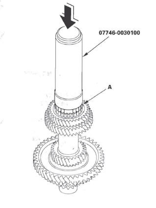
2. Slide the 3rd gear (A) over the countershaft, and press it in place using the driver (40 mm I.D.) and a press.
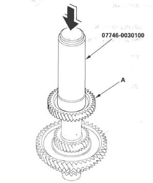
3. Install the cotters, 35 x 47 x 7.8 mm collar; set ring, needle bearing, and 4th gear.
4. Slide the reverse selector hub (A) over the countershaft, then press it in place using the driver (40 mm I.D.) and a press.
NOTE: Some reverse selector hubs are not press-fitted and can be installed without using the driver (40 mm I.D.) and a press.
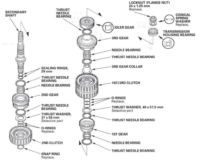
Secondary Shaft Disassembly, Inspection, and Reassembly
1. Inspect the thrust needle bearing and the needle bearing for galling and rough movement.
2. Inspect the splines for excessive wear and damage.
3. Check shaft bearing surface for scoring and excessive wear.
4. Before installing the O-rings, wrap the shaft splines with tape to prevent O-ring damage.
5. Lubricate all parts with ATF during assembly.
6. Install the conical spring washer, idler gear in the direction shown.
7. Replace the locknut and conical spring washer with new ones when assembling the transmission. The locknut has left-hand threads.
8. Check the 2nd gear clearance and 1st gear clearance.
Secondary Shaft Ball Bearing, Idler Gear Removal and Installation
Special Tools Required
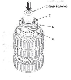
Attachment, 42 mm I.D. 07QAD-P0A0100
Removal
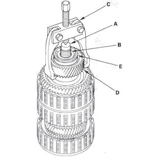
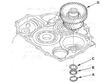
Place a shaft protector (A) on the secondary shaft (B), and set the puller (C) under the idler gear (D), then remove the idler gear and ball bearing (E).
Installation
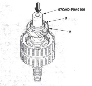
Install the idler gear (A) on the secondary shaft (B), and install the ball bearing (C) over the idler gear using the attachment (42 mm I.D.) and a press.
Secondary Shaft 2nd Gear Axial Clearance Inspection
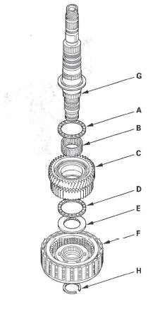
1. Install the thrust needle bearing (A), needle bearing (B), 2nd gear (C), thrust needle bearing (D), 37 x 58 mm thrust washer (E), and 2nd clutch (F) on the secondary shaft (G), then secure them with the snap ring (H). Do not install the O-rings during inspection.
2. Measure the clearance between the snap ring (A) and the 2nd clutch guide (B) with a feeler gauge (C), in at least three places. Use the average as the actual clearance.
Standard: 0.04-0.12 mm (0.002-0.005 in.)
3. If the clearance is out of standard, remove the 37 x 58 mm thrust washer and measure its thickness.
4. Select and install a new thrust washer, then recheck.
THRUST WASHER, 37 x 58 mm
5. After replacing the thrust washer, make sure the clearance is within standard.
6. Disassemble the shaft and gears.
Secondary Shaft 1st Gear Axial Clearance Inspection
Special Tools Required
Attachment, 42 mm I.D. 07QAD-POA0100
1. Install the thrust needle bearing (A), needle bearing (B), 1st gear (C), thrust needle bearing (D), 40 x 51.5 mm thrust washer (E), 1st/3rd clutch (F), and 3rd gear collar (G) on the secondary shaft (H).
Do not install the O-rings during inspection.
2. Install the idler gear (A), then install the ball bearing (B) on the idler gear using the attachment (42 mm I.D.) and a press.
3. Install the conical spring washer and locknut, then tighten the locknut to 29 N*m (3.0 kgf*m, 22 Ibf*ft).
4. Turn the secondary shaft assembly upside down, and set the dial indicator (A) on the 1st gear (B).
5. Lift the 1st gear (A) up while holding the secondary shaft, and use the dial indicator (B) to read the 1st gear axial clearance.
6. Measure the 1 st gear axial clearance in at least three places while moving the 1st gear. Use the average as the actual clearance.
Standard: 0.04-0.12 mm (0.002-0.005 in.)
7. If the clearance is out of standard, remove the 40 x 51.5 mm thrust washer and measure its thickness.
8. Select and install a new thrust washer, then recheck.
THRUST WASHER, 40 x 51.5 mm
9. After replacing the thrust washer, make sure the clearance is within standard.
10. Disassemble the shaft and gears.
Idler Gear Shaft Removal and Installation
1. Remove the snap ring (A), cotter retainer (B), and cotter keys (C). Do not distort the snap ring.
2. Remove the idler gear shaft/idler gear assembly (D) from the transmission housing.
3. Check the snap rings and cotter retainer for wear and damage. Replace them if they are worn, distorted, or damaged.
4. Install the idler gear and shaft in the reverse order of removal.
Idler Gear/Idler Gear Shaft Replacement
Special Tools Required
- Attachment, 32 x 35 mm 07746-0010100
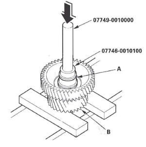
- Driver 07749-0010000
1. Remove the snap ring from the idler gear/idler shaft assembly.
2. Remove the idler gear shaft (A) from the idler gear (B) using the driver, the attachment (32 x 35 mm), and a press.
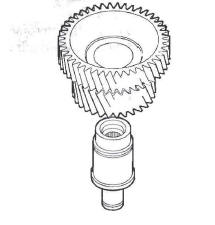
3. Replace the idler gear or idler gear shaft, and attach the idler gear shaft to the idler gear.
4. Install the idler gear shaft (A) in the idler gear (B) using the driver, the attachment (32 x 35 mm), and a press.
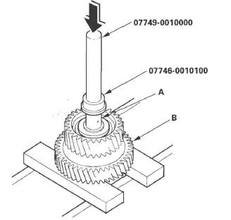
5. Install the snap ring.
1st, 2nd, and 3rd Clutch Disassembly
NOTE: The 1st, 2nd, and 3rd clutch packs have a clutch pressure release cavity between the spring retainer and clutch piston. An oil seal is installed on the circumference of the spring retainer, and seals the clutch piston. If you remove the spring retainer from the piston, it will damage the oil seal when reinstalling the retainer on the piston.
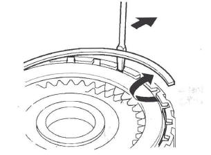
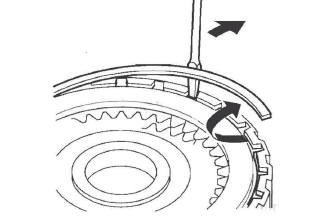
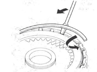
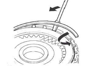
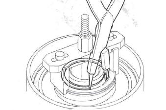
1. Remove the snap ring with a screwdriver.
2. Remove the clutch end plate (A), clutch discs (B) (5), clutch wave-plates (C) (4), clutch flat-plate (D) (1), and wave spring (E) from the 1st clutch drum (F).
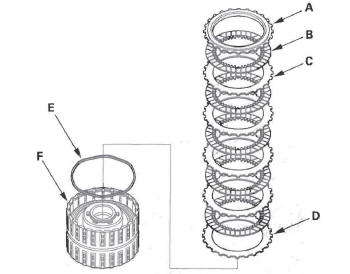
3. Make a reference mark on the flat-plate.
4. Remove the clutch end plate (A), clutch discs (B) (6), clutch wave-plates (C) (5), clutch flat-plate (D) (1), and wave spring (E) from the 2nd clutch drum (F).
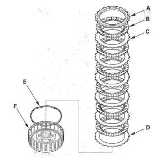
5. Make a reference mark on the flat-plate.
6. Remove the clutch end plate (A), clutch discs (B) (6), clutch wave-plates (C) (5), clutch flat-plate (D) (1), and wave spring (E) from the 3rd clutch drum (F).
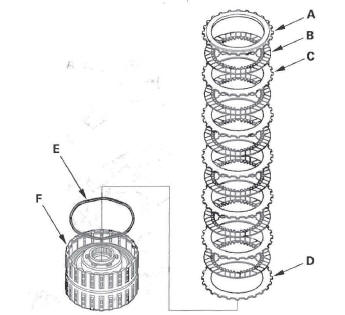
7. Make a reference mark on the flat-plate.
4th and 5th Clutch Disassembly
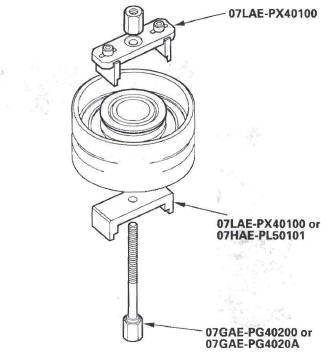
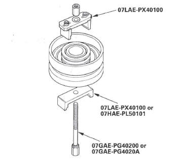
Special Tools Required
- Clutch spring compressor attachment 07LAE-PX40100 or 07HAE-PL501 01
- Clutch spring compressor bolt assembly 07GAE-PG40200 or 07GAE-PG4020A
1. Remove the snap ring with a screwdriver.
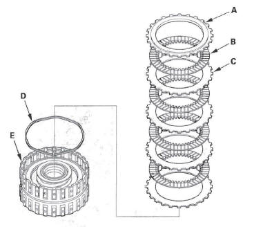
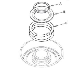
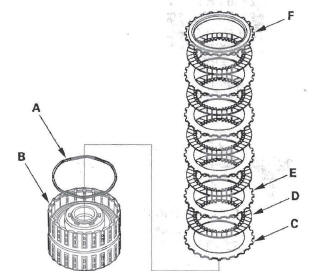
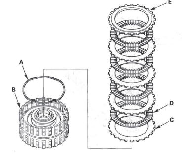
2. Remove the clutch end plate (A), clutch discs (B) (4), clutch wave-plates (C) (4), and wave spring (D) from the 4th clutch drum (E).
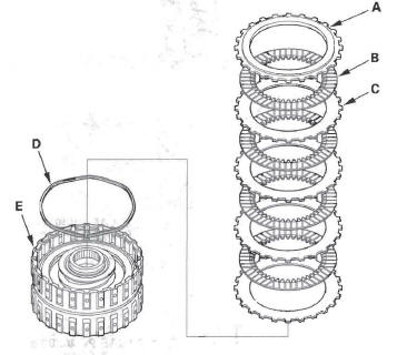
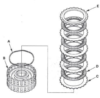
3. Remove the clutch end plate (A), clutch discs (B) (4), clutch wave-plates (C) (4), and wave spring (D) from the 5th clutch drum (E).
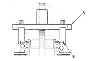
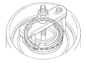
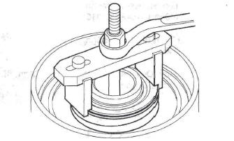
4. Install the clutch spring compressor attachments and the clutch spring compressor bolt assembly.
5. Be sure the clutch spring compressor attachment (A) is adjusted to have full contact with the return spring retainer (B).
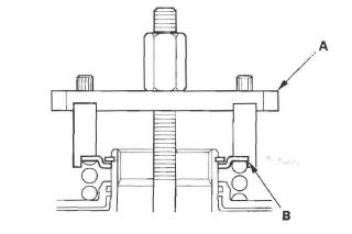
6. If either end of the clutch spring compressor attachment is set over an area of the spring retainer that is unsupported by the return spring, the retainer may be damaged.
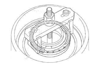
7. Compress the return spring until the snap ring can be removed.
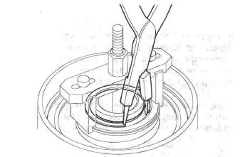
8. Remove the snap ring with the snap ring pliers.
9. Remove the clutch spring compressor attachments and the clutch spring compressor bolt assembly.
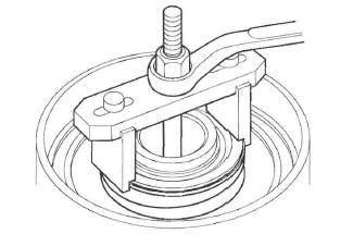
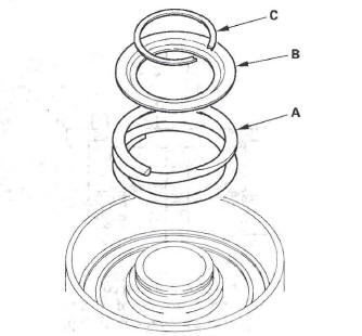
10. Remove the snap ring (A), spring retainer (B), and return spring (C).
11. Wrap a shop rag around the clutch drum, and apply air pressure to the fluid passage to remove the piston. Place a finger tip on the other passage while applying air pressure.
12. Remove the clutch piston (A), and remove the outer O-ring (B) and inner O-ring (C) from the piston.
Clutch Inspection
1. Inspect the 4th and 5th clutch pistons and clutch piston check valves (A).
2. If the clutch piston check valve is loose or damaged, replace the clutch piston.
3. Check the spring retainer for wear and damage.
4. Inspect the clutch discs, clutch-plates, and clutch end plate for wear, damage, and discoloration.
Standard Thickness:
Clutch Discs: 1.94 mm (0.076 in.)
Clutch Plates:
1st clutch (wave-plates): 1.6 mm (0.063 in.)
2nd clutch: Wave-plates: 2.0 mm (0.079 in.)
Flat-plate: 2.0 mm (0.079 in.)
3rd clutch: Wave-plates: 1.6 mm (0.063 in.)
Flat-plates: 1.6 mm (0.063 in.)
4th clutch (wave-plates): 2.0 mm (0.079 in.)
5th clutch (wave-plates): 2.0 mm (0.079 in.)
5. If the clutch discs are worn or damaged, replace them as a set. If the clutch discs are replaced, inspect the clutch end-plate-to-top disc clearance.
6. If any plate is worn, damaged, or discolored, replace the damaged plate with the new plate, and inspect the other wave-plates for a phase difference. If the clutch plate is replaced, inspect the clutch end-plate-to-top disc clearance.
7. If the clutch end plate is worn, damaged, or discolored, inspect the clutch end-plate-to-top disc clearance, then replace the clutch end plate.
Clutch Wave-plate Phase Difference Inspection
1. Place the clutch wave-plate (A) on a surface plate, and set a dial indicator (B) on the wave-plate.
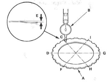
2. Find the bottom (C) of a phase difference of the wave-plate, zero the dial indicator and make a reference mark on the bottom of the wave-plate.
3. Rotate the wave-plate about 60-degrees apart from the bottom while holding the wave-plate by its circumference. The dial indicator should be at the top (D) of a phase difference. Do not rotate the wave-plate while holding its surface, always rotate it with holding its circumference.
4. Read the dial indicator. The dial indicator reads the phase difference (E) of the wave-plate between bottom and top.
Standard Phase Difference:
1st clutch: 0.15-0.25 mm (0.006-0.010 in.)
2nd clutch: 0.1-0.2 mm (0.004-0.008 in.)
3rd clutch: 0.1-0.2 mm (0.004-0.008 in.)
4th clutch: 0.1-:0.2 mm (0.004-0.008 in.)
5th clutch: 0.1-0.2 mm (0.004-0.008 in.)
5. Rotate the wave-plate about 60-degrees. The dial indicator should be at the bottom of a phase difference (F and G), and zero the dial indicator.
G. Measure the phase difference at the other two tops (H and I) of the wave-plate by following steps 3 thru 5.
7. If the two values of the three measurements are within the standard, the wave-plate is OK. If the two values of the three measurements are out of the standard, replace the wave-plate.
Clutch Clearance Inspection
Special Tools Required
Clutch compressor attachment 07ZAE-PRP0100
1. Inspect the clutch piston, discs, plates, and end plate for wear and damage (see page 14-366), and inspect the clutch wave-plate phase difference, if necessary.
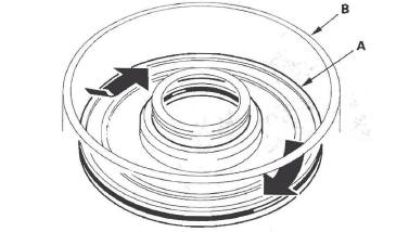
2. Install the wave spring (A) in the 1 st clutch drum (B).
Install the clutch flat-plate (C) (1), then starting with the clutch disc, alternately install the discs (D) (5) and wave-plates (E) (4). Install the clutch end-plate (F) with the flat side down on the top disc.
3. Install the wave spring (A) in the 2nd clutch drum (B). Install the clutch flat-plate (C) (1), then starting with the clutch disc, alternately install the discs (D) (6) and wave-plates (E) (5). Install the clutch endplate (F) with the flat side down on the top disc.
4. Install the wave spring (A) in the 3rd clutch drum (B). Install the clutch flat-plate (C) (1), then starting with the clutch disc, alternately install the discs (D) (6) and wave-plates (E) (5). Install the clutch endplate (F) with the flat side down on the top disc.
5. Install the clutch pistons in the 4th and 5th clutch drums. Do not install the O-rings during inspection.
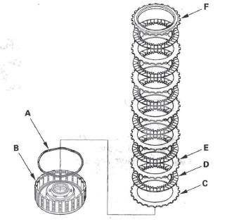
6. Install the wave spring (A) in the 4th clutch drum (B). Starting with the clutch wave-plate, alternately install the wave-plates (C) (4) and discs (D) (4).
Install the clutch end-plate (E) with the flat side down on the top disc.
7. Install the wave spring (A) in the 5th clutch drum (B). Starting with the clutch wave-plate, alternately install the wave-plates (C) (4) and discs (D) (4).
Install the clutch end-plate (E) with the flat side down on the top disc.
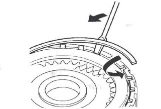
8. Install the snap ring with a screwdriver to secure the clutch end-plate.
9. Set a dial indicator (A) on the clutch end-plate (B).
10. Zero the dial indicator with the clutch end-plate lifted up to the snap ring (C).
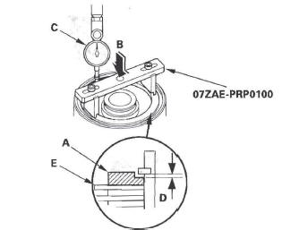
11. Release the clutch end-plate to lower the clutch end-plate, then put the special tool on the end-plate (A).
12. Press the clutch compressor attachment down with 150-160 N (15-16 kgf, 33-35Ibf) (B) using a force gauge, and read the dial indicator (C). The dial indicator reads the clearance (D) between the clutch end-plate and top disc (E). Take measurements in at least three places, and use the average as the actual clearance.
Clutch End-Plate-to-Top Disc Clearance
Service limit:
1st Clutch: 1.38-1.58 mm (0.054-0.062 in.)
2nd Clutch: 1.18-1.38 mm (0.046-0.054 in.)
3rd Clutch: 1.23-1.43 mm (0.048-0.056 in.)
4th Clutch: 0.93-1.13 mm (0.037-0.044 in.)
5th Clutch: 0.93-1.13 mm (0.037-0.044 in.)
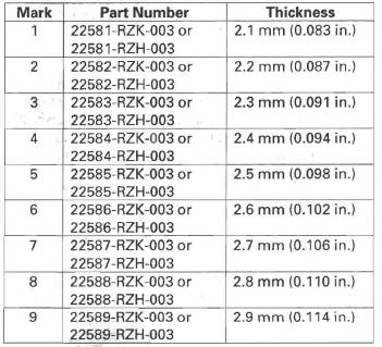
13. If the clearance is out of the service limit, select a new clutch end-plate from the following tables.
1ST and 2ND CLUTCH END PLATES
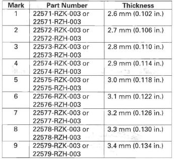
3RD CLUTCH END PLATES
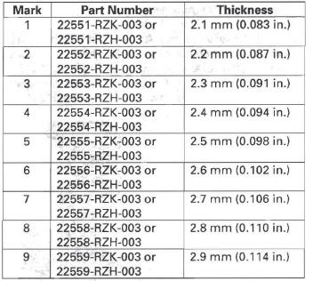
4TH and 5TH CLUTCH END PLATES
14. Install the new clutch end-plate, and recheck the clearance. If the thickest clutch end-plate is installed, but the clearance is still over the service limit, replace the clutch discs and plates.
1st, 2nd, and 3rd Clutch Reassembly
1. Soak the clutch discs thoroughly in ATF for a minimum of 30 minutes.
2. Install the wave spring (A) in the 1st clutch drum (B).
Install the clutch flat-plate (C) (1), then starting with the clutch disc, alternately install the discs (D) (5) and wave-plates (E) (4). Install the clutch end-plate (F) with the flat side down on the top disc.
3. Install the wave spring (A) in the 2nd clutch drum (B). Install the clutch flat-plate (C) (1), then starting with the clutch disc, alternately install the discs (D) (6) and wave-plates (E) (5). Install the clutch endplate (F) with the flat side down on the top disc.
4. Install the wave spring (A) in the 3rd clutch drum (B). Install the clutch flat-plate (C) (1), then starting with the clutch disc, alternately install the discs (D) (6) and wave-plates (E) (5). Install the clutch endplate (F) with the flat side down on the top disc.
5. Install the snap ring with a screwdriver to secure the clutch end-plate.
6. Check that the clutch piston moves by applying air pressure into fluid passage.
4th and 5th Clutch Reassembly
Special Tools Required
- Clutch spring compressor bolt assembly 07GAE-PG40200 or 07GAE-PG4020A
- Clutch spring compressor attachment 07LAE-PX40100 or 07HAE-PL50101
1. Soak the clutch discs thoroughly in ATF for a minimum of 30 minutes.
2. Install the new O-rings (A) on the clutch piston (B).
Do not twist the O-rings.
3. Install the clutch piston (A) in the clutch drum (B) while applying pressure and rotating to ensure proper seating. Do not pinch the O-ring.
4. Install the return spring (A) and spring retainer (B), and position the snap ring (C) on the spring retainer.
5. Install the clutch spring compressor attachments and the clutch spring compressor bolt assembly.
6. Be sure the clutch spring compressor attachment (A) is adjusted to have full contact with the spring retainer (B).
7. If either end of the clutch spring compressor attachment is set over an area of the spring retainer that is unsupported by the return spring, the retainer may be damaged.
8. Compress the return spring until the snap ring can be installed.
9. Install the snap ring with the snap ring pliers.
10. Remove the clutch spring compressor attachments and the clutch spring compressor bolt assembly.
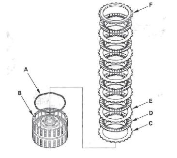
11. Install the wave spring (A) in the 4th clutch drum (B). Starting with the clutch wave-plate, alternately install the wave-plates (C) (4) and discs (D) (4).
Install the clutch end-plate (E) with the flat side down on the top disc.
12. Install the wave spring (A) in the 5th clutch drum (B). Starting with the clutch wave-plate, alternately install the wave-plates (C) (4) and discs (D) (4).
Install the clutch end-plate (E) with the flat side down on the top disc.
13. Install the snap ring with a screwdriver to secure the clutch end-plate.
14. Check that the clutch piston moves by applying air pressure into fluid passage.
READ NEXT:
 A/T Differential
Component Location Index
4WD
2WD
Backlash Inspection
NOTE: The illustration shows the 4WD model; 2WD is
similar.
1. Install the drive shaft and intermediate shaft into
the differential assembly.
2
Transfer Assembly Inspection/Disassembly/Reassembly
Inspection
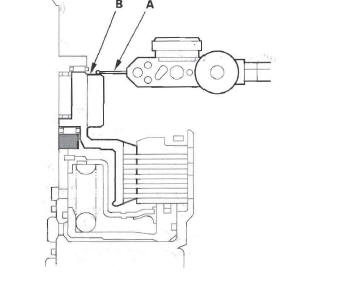
1. Set the dial indicator (A) on the companion flange
(B).
2. Measure the transfer gear backlash.
Standard: 0.06-0.16 mm (0.02-0.06 in.)
3. Secure the transfer housing (A) in a bench vise
Rear Differential
Special Tools
Holder Handle
Oil Seal Driver
Attachment, 78 x 80 mm
Attachment, 52 x 55 mm
Companion Flange Holder
Driver
Component Location Index
REAR DIFFERENTIAL MOUNT
Replacement
SEE MORE:
MICU Input Test
NOTE:
The MICU turns on the headlights (high beams) in a dim mode for the
daytime running lights under the following
conditions:
The ignition switch is ON (II)
The headlight switch is OFF
The parking brake is released (parking brake switch OFF)
If the vehicle is equipped with an opti
Rear Seat Adjustments
To adjust the seats forward and
backward, pull up on the lever under
the seat cushion. After moving the
seat, make sure it is locked into
position.
The angle of each rear seat-back can
be adjusted separately. To change
the seat-back angle of the rear seatback,
pull up on the relea
