Honda CR-V: Valve Body
Valve Body and ATF Strainer Removal
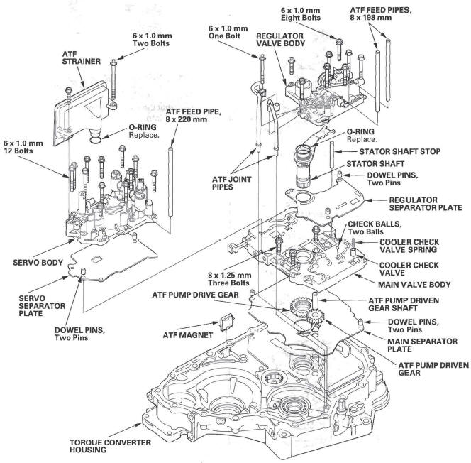
NOTE: The illustration shows the 4WD transmission; the 2WD is similar.
1. Remove the ATF feed pipes (A) and ATF joint pipes (B).
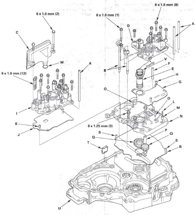
2. Remove the ATF strainer (C) (two bolts), 3. Remove the regulator valve body (D) (eight bolts),
4. Remove the stator shaft (E) and stator shaft stop (F), then remove the regulator separator plate (G) and two dowel pins (H).
5. Remove the servo body (I) (12 bolts), then remove the separator plate (J) and two dowel pins (K).
6. Remove the cooler check valve spring (L) and valve (M), then remove the main valve body (N) (three bolts). Do not let the check balls (O) fall out.
7. Remove the ATF pump driven gear shaft (P), then remove the ATF pump gears (Q).
8. Remove the main separator plate (R) and two dowel pins (S).
9. Remove the ATF magnet (T), clean and reinstall it in the torque converter housing (U).
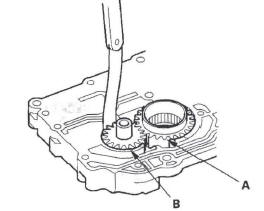
10. Clean the inlet opening (A) of the ATF strainer (B) thoroughly with compressed air, then check that it is in good condition and that the inlet opening is not clogged.
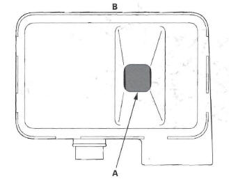
11. Test the ATF strainer by pouring clean ATF through the inlet opening, and replace it if it is clogged or damaged.
12. Remove the O-rings (V) (W) from the stator shaft and ATF strainer. Install the new ones when installing the valve bodies.
Valve Body Repair
NOTE: This repair is only necessary if one or more of the valves in a valve body do not slide smoothly in their bores. Use this procedure to free the valves.
1. Soak a sheet of # 600 abrasive paper in ATF for about 30 minutes.
2. Carefully tap the valve body so the sticking valve drops out of its bore. It may be necessary to use a small screwdriver to pry the valve free. Be careful not to scratch the bore with the screwdriver.
3. Inspect the valve for any scuff marks. Use the ATF soaked # 600 paper to polish off any burrs that are on the valve, then wash the valve in solvent and dry it with compressed air.
4. Roll up half a sheet of ATF-soaked # 600 paper and insert it in the valve bore of the sticking valve.
Twist the paper slightly, so that it unrolls and fits the bore tightly, then polish the bore by twisting the paper as you push it in and out.
NOTE: The valve body is aluminum and doesn't require much polishing to remove any burrs.
5. Remove the # 600 paper. Thoroughly wash the entire valve body in solvent, then dry it with compressed air.
6. Coat the valve with ATF, then drop it into its bore. It should drop to the bottom of the bore under its own weight. If not, repeat step 4, then retest. If the valve still sticks, replace the valve body.
7. Remove the valve, and thoroughly clean it and the valve body with solvent. Dry all parts with compressed air, then reassemble using ATF as a lubricant.
Valve Body Valve Installation
1. Coat all parts with ATF before assembly.
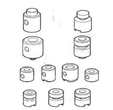
2. Install the valves and springs in the sequence shown for the main valve body, regulator valve body, and servo body. Refer to the following valve cap illustrations, and install each valve cap so the end shown facing up will be facing the outside of the valve body.
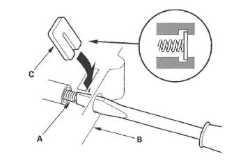
3. Install all the springs and seats. Insert the spring (A) in the valve, then install the valve in the valve body (B). Push the spring in with a screwdriver, then install the spring seat (C).
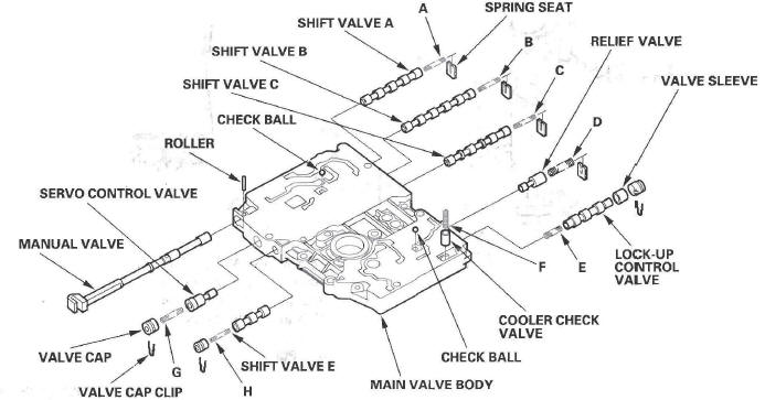
Main Valve Body Disassembly, Inspection, and Reassembly
1. Clean all parts thoroughly in solvent, and dry them with compressed air. Blow out all passages.
2. Do not use a magnet to remove the check balls, it may magnetize the balls.
3. Inspect the valve body for scoring and damage.
4. Check all valves for free movement. If any fail to slide freely, refer to valve body repair.
5. Coat all parts with ATF during assembly.
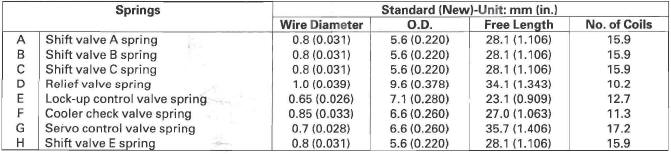
SPRING SPECIFICATIONS
ATF Pump Inspection
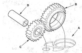
1. Install the ATF pump drive gear (A), driven gear (B), and ATF pump driven gear shaft (C) in the main valve body (D). Lubricate all parts with ATF, and install the ATF pump driven gear with its grooved and chamfered side facing up.
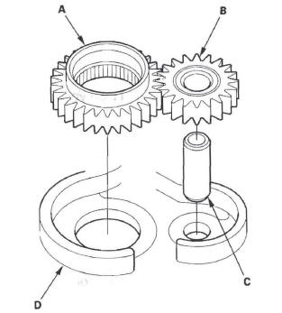
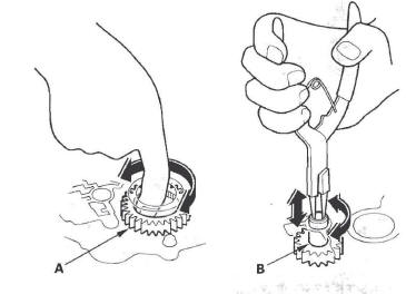
2. Measure the side clearance of the ATF pump drive gear (A) and driven gear (B).
ATF Pump Gears Side (Radial) Clearance:
Standard (New):
ATF Pump Drive Gear:
0.210-0.265 mm (0.0083-0.0104 in.)
ATF Pump Driven Gear:
0.070-0.125 mm (0.0028-0.0049 in.)
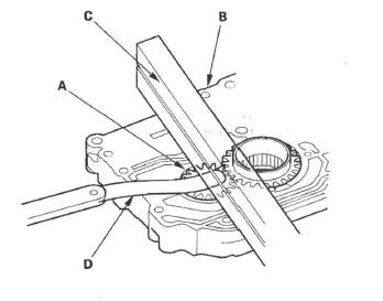
3. Remove the ATF pump driven gear shaft. Measure the thrust clearance between the ATF pump driven gear (A) and the valve body (B) with a straight edge (C) and a feeler gauge (D).
ATF Pump Drive/Driven Gear Thrust (Axial)
Clearance:
Standard (New): 0.03-0.06 mm (0.001-0.002 in.)
Service limit: 0.07 mm (0.003 in.)
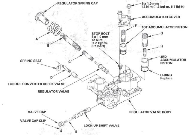
Regulator Valve Body Disassembly, Inspection, and Reassembly
1. Clean all parts thoroughly in solvent, and dry them with compressed air. Blow out all passages.
2. Inspect the valve body for scoring and damage, and check all valves for free movement. If any fail to slide freely, refer to valve body repair.
3. Hold the regulator spring cap in place while removing the stop bolt. The regulator spring cap is spring loaded.
4. Coat all parts with ATF during assembly.
5. When reassembling the valve body, align the hole in the regulator spring cap with the hole in the valve body, then press the spring cap into the valve body, and tighten the stop bolt.
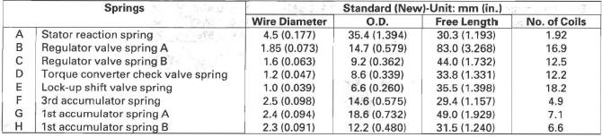
SPRING SPECIFICATIONS
Servo Body Disassembly, Inspection, and Reassembly
1. Clean all parts thoroughly in solvent, and dry them with compressed air. Blow out all passages.
2. Inspect the valve body for scoring and damage.
3. Check the shift valve D for free movement. If any fail to slide freely, refer to valve body repair.
4. When removing and installing the shift solenoid valves, refer to shift solenoid valves removal and installation.
5. Coat all parts with ATF during assembly.
6. Replace the O-rings with new ones.
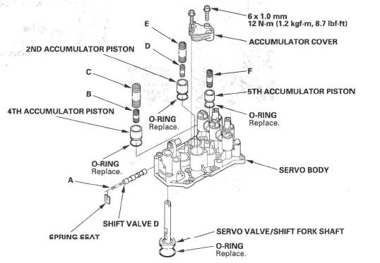
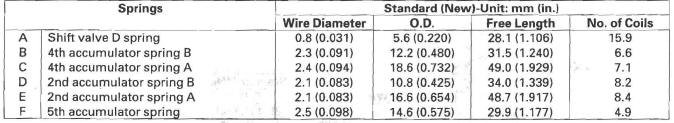
SPRING SPECIFICATIONS
Shift Solenoid Valve Removal and Installation
NOTE:
- Do not hold the shift solenoid connector to remove and to install the shift solenoid valves. Hold the shift solenoid valve body.
- Do not install shift solenoid valve A before installing shift solenoid valve D, and do not install shift solenoid valve B before solenoid valve E. If solenoid valves A and B are installed before solenoid valves D and E, it may damage the hydraulic control system.
1. Remove the shift solenoid valves by holding the solenoid valve body.
2. Install new O-rings (F) on each shift solenoid valves.
NOTE: A new solenoid valve comes with new O-rings. If you install a new solenoid valve, use the O-rings provided on it.
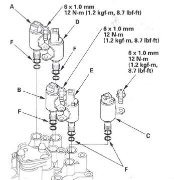
3. Install shift solenoid valve D by holding the shift solenoid valve body; be sure to install mounting bracket contacts the servo body.
4. Install shift solenoid valve A by holding the shift solenoid valve body; be sure to install mounting bracket contacts the bracket on shift solenoid valve D.
5. Install shift solenoid valve E by holding the shift solenoid valve body; be sure to install mounting bracket contacts the servo body.
6. Install shift solenoid valve B by holding the shift solenoid valve body; be sure to install mounting bracket contacts the bracket on shift solenoid valve E.
7. Install shift solenoid valve C by holding the shift solenoid valve body; be sure to install mounting bracket contacts the servo body.
Valve Body and ATF Strainer Installation
NOTE: The illustration shows the 4WD transmission; the 2WD is similar.
1. Make sure that the ATF magnet is cleaned and installed in the torque converter housing.
Torque Specifications
6 x 1.0 mm: 12 N*m (1.2 kgf.m, 8.7Ibf*ft)
8 x 1.25 mm: 18 N*m (1.8 kgf*m, 13Ibf*ft)
2. Install the main separator plate (A) and two dowel pins on the torque converter housing. Then install the ATF pump drive gear (B), driven gear (C), and ATF pump driven gear shaft (D). Install the ATF pump driven gear with its grooved and chamfered side facing down.
3. Install the main valve body.
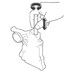
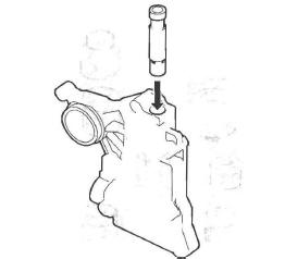
4. Make sure the ATF pump drive gear (A) rotates smoothly in the normal operating direction, and the ATF pump driven gear shaft (B) moves smoothly in the axial and normal operating direction.
5. If the ATF pump drive gear and ATF pump driven gear shaft do not move smoothly, loosen the main valve body bolts. Realign the ATF pump driven gear shaft, and retighten the bolts to the specified torque, then recheck. Failure to align the ATF pump driven gear shaft correctly will result in a seized ATF pump drive gear or ATF pump driven gear shaft.
6. Make sure that the two check balls and the cooler check valve are in the main valve body, then install the cooler check valve spring in the cooler check valve.
7. Install the servo separator plate and two dowel pins on the main valve body.
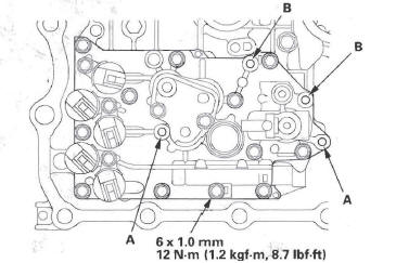
8. Install the servo body (12 bolts). Install the ATF strainer with the two bolts in the bolt holes (A) in step 12, and install the baffle plate with the two bolts in the bolt holes (B) in step 2 in shaft assemblies and housing installation.
9. Install the regulator separator plate and two dowel pins on the main valve body.
10. Install the new O-ring on the stator shaft, and install the stator shaft and stator shaft stop.
11. Install the regulator valve body (eight bolts).
12. Install the new O-ring on the ATF strainer, and install the ATF strainer (two bolts).
13. Install the ATF joint pipes (one bolt).
14. Install the ATF feed pipes in the regulator valve body and servo body.
READ NEXT:
 Torque Converter Housing
Mainshaft Bearing and Oil Seal
Replacement
Special Tools Required
Adjustable bearing puller, 25-40 mm
07736-A01000B or 07736-A01000A
Attachment, 62 x 68 mm 07746-0010500
Attachment, 72 x 75 mm 0
Shafts and Clutches
Mainshaft Disassembly, Inspection, and Reassembly
1. Inspect the thrust needle bearing and the needle bearing for galling and
rough movement.
2. Inspect the splines for excessive wear and damage.
3
A/T Differential
Component Location Index
4WD
2WD
Backlash Inspection
NOTE: The illustration shows the 4WD model; 2WD is
similar.
1. Install the drive shaft and intermediate shaft into
the differential assembly.
2
SEE MORE:
Transmission Mount Replacement
1. Loosen the upper torque rod mounting bolt (A).
2. Remove the air cleaner housing assembly.
3. Remove the powertrain control module (PCM)
cover, then remove the three bolts securing the
PCM.
4. Remove the PCM bracket.
5. Support the transmission with a jack and wood
block under the transmissio
Voice Control System
You can select the AUX mode by
using the navigation system voice
control buttons, but cannot operate
the play mode functions.
The specifications for compatible
MP3 files are:
Sampling frequency:
32/44.1/48 kHz (MPEG1)
16/22.05/24 kHz (MPEG2)
Bitrate:
32/40/48/56/64/80/96/112/128/160/19
