Honda CR-V: Side Engine Mount Replacement
1. Support the engine with a jack and wood block under the oil pan.
2. Remove the power steering (P/S) fluid reservoir from the holder.
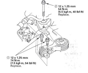
3. Remove the upper torque rod.
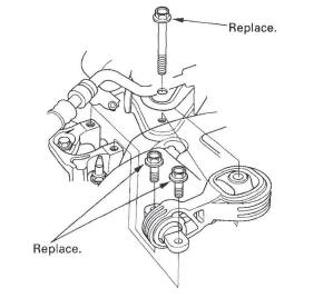
4. Remove the ground cable (A), then remove the side engine mount bracket (B).
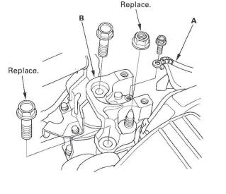
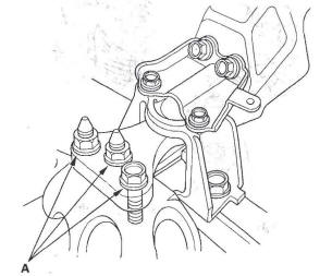
5. Remove the side engine mount stiffener (A), then remove the side engine mount (B).
6. Install the side engine mount, then install the side engine mount stiffener.
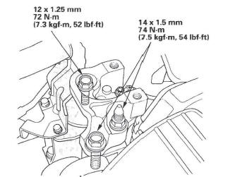
7. Install the side engine mount bracket (A), then loosely tighten the new bolt and nut (B), and loosely tighten the bolt (C).
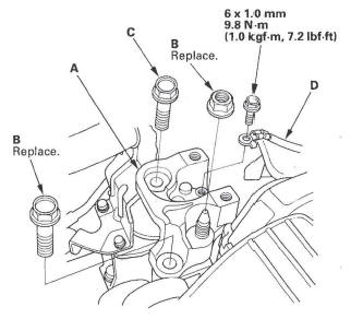
8. Install the ground cable (D).
9. Remove the air cleaner housing assembly.
10. Loosen the transmission mounting bolt and nuts (A).
11. Raise the lift to full height.
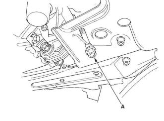
12. Loosen the lower torque rod mounting bolt (A).
13. Lower the vehicle on the lift.
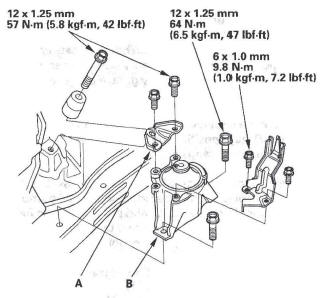
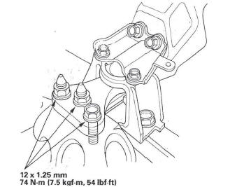
14. Tighten the side engine mount mounting bolts and nut.
15. Tighten the transmission mounting bolt and nuts.
16. Raise the lift to full height.
17. Tighten the lower torque rod mounting bolt.
18. Lower the vehicle on the lift.
19. Install the air cleaner housing assembly.
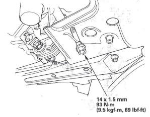
20. Install the upper torque rod, then tighten the new upper torque rod mounting bolts in the numbered sequence shown.
READ NEXT:
 Transmission Mount Replacement
1. Loosen the upper torque rod mounting bolt (A).
2. Remove the air cleaner housing assembly.
3. Remove the powertrain control module (PCM)
cover, then remove the three bolts securing the
PCM.
4. R
Side Engine Mount Bracket Replacement
1. Support the engine with a jack and wood block
under the oil pan.
2. Remove the upper torque rod.
3. Remove the ground cable (A), then remove the side
engine mount bracket (B).
4. Install the sid
Cylinder Head
Special Tools
Air Pressure Regulator
Valve Guide Reamer, 5.5 mm
Socket, 19 mm
Holder Handle
Adjuster
Locknut Wrench
Stem Seal Driver
VTEC Air Adapter
VTEC Air Stopper
Air Joint Adapter
C
SEE MORE:
Cylinder Head Installation
1. Install a new coolant separator in the engine block
whenever the engine block is replaced.
2. Clean the cylinder head and block surface.
3. Install the new cylinder head gasket (A) and dowel
pins (B) on the engine block. Always use a new
cylinder head gasket.
Set the crankshaft to top dead cen
Checking Loads
The best way to confirmthat all
loads are within limits is to check
them at a public scale. For public
scales in your area, check your local
phone book, or contact your trailer
dealer or rental agency for
assistance.
If you cannot get to a public scale,
you can estimate the total trai
