Honda CR-V: Seat Heaters
Component Location Index
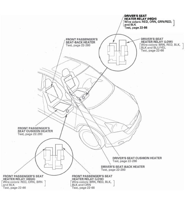
- DRIVER'S SEAT HEATER RELAY (HIGH)
- DRIVER'S SEAT HEATER RELAY (LOW)
- DRIVER'S SEAT CUSHION HEATER
- DRIVER'S SEAT-BACK HEATER
- FRONT PASSENGER'S SEAT-BACK HEATER
- FRONT PASSENGER'S SEAT CUSHION HEATER
- FRONT PASSENGER'S SEAT HEATER RELAY (HIGH)
- FRONT PASSENGER'S SEAT HEATER RELAY (LOW)
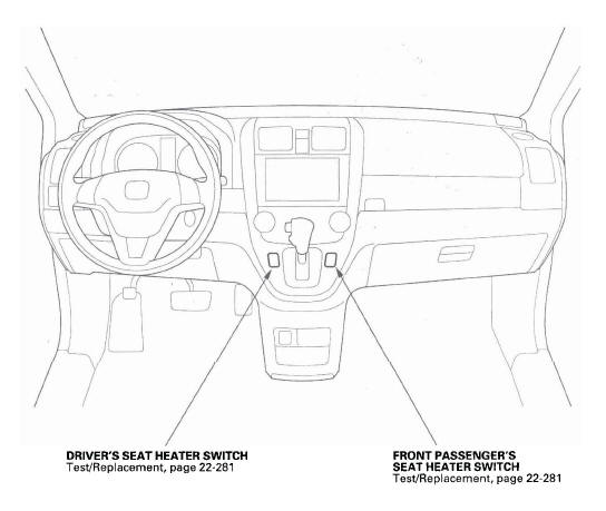
- DRIVER'S SEAT HEATER SWITCH
- FRONT PASSENGER'S SEAT HEATER SWITCH
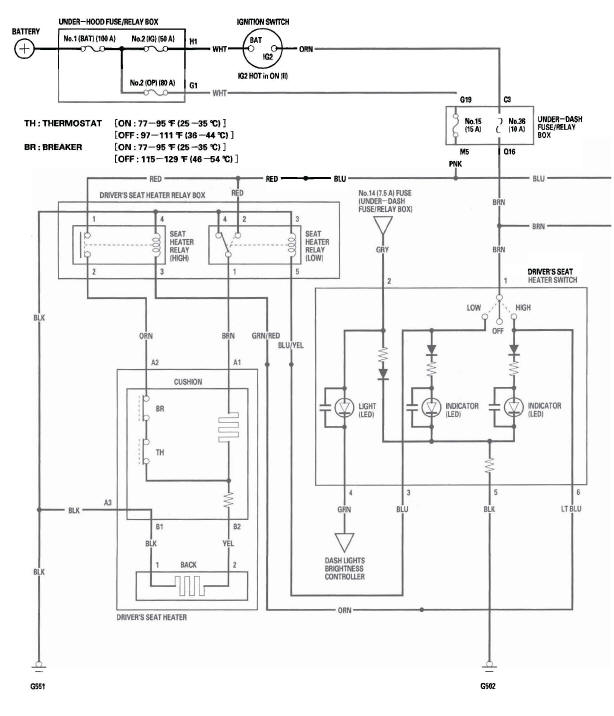
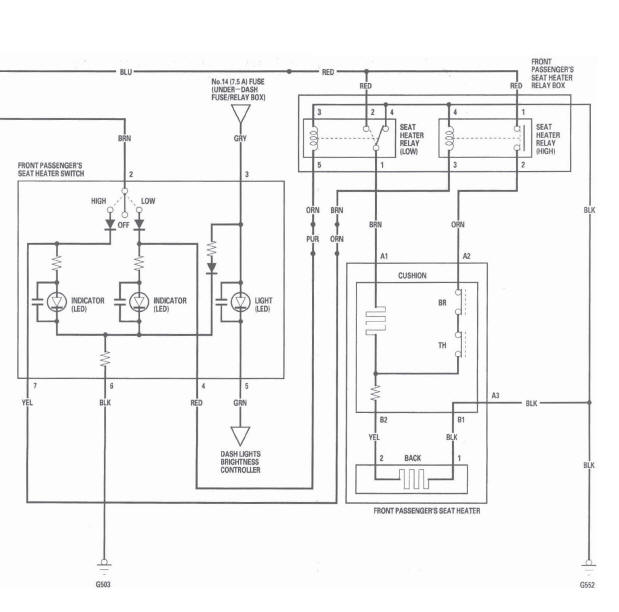
Circuit Diagram
Seat Heater Test
1. Remove the driver's or front passenger's seat.
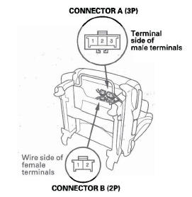
2. Disconnect the 3P (A) and 2P (B) connectors from the seat heater.
Driver's Seat
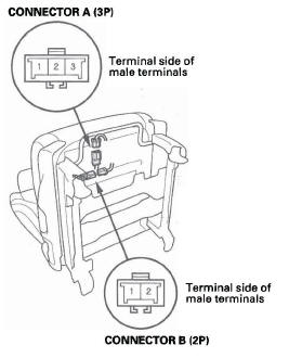
Front Passenger's Seat
3. Check for continuity between the seat heater connector B (2P) No.1 and No.2 terminals. There should be continuity.
4. Reconnect the seat heater connector B (2P) to the seat-back heater.
5. Check for continuity between the seat heater connector A (3P) No.1 and No.2 terminals, No.2 and No.3 terminals, and No.1 and No.3 terminals.
There should be continuity.
6. If the continuity is not as specified, replace the appropriate seat heater.
Switch Test/Replacement
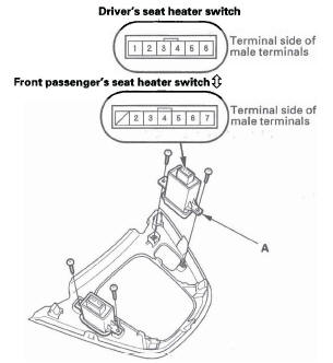
1. Remove the shift lever panel.
2. Disconnect the 6P (or 7P) connector from the seat heater switch (A), then remove the switch.
* : Front passenger's
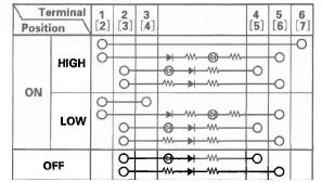
3. Check for continuity between the terminals in each switch position according to the table.
 : Front
passenger's seat heater switch
: Front
passenger's seat heater switch
4. If the continuity is not as specified, replace the switch.
READ NEXT:
 Rear Window Defogger
Component Location Index
UNDER-DASH FUSE/
RELAY BOX
UNDER-HOOD FUSE/RELAY BOX
REAR WINDOW DEFOGGER RELAY
HVAC CONTROL UNIT
REAR WINDOW DEFOGGER SWITCH/
MIRROR DEFOGGER SWITCH
REAR WINDOW DEF
Immobilizer System
Component Location Index
IMMOBILIZER INDICATOR
IMMOBILIZER-KEYLESS CONTROL UNIT (Built-in receiver)
UNDER-DASH
FUSE/RELAY BOX
IMOES UNIT
(Built into the MICU)
PCM
IGNITION KEY
TRANSPONDE
SEE MORE:
Remote Audio Controls
If equipped
Three controls for the audio system
are mounted in the steering wheel
hub. These let you control basic
functions without removing your
hand from the wheel.
The VOL button adjusts the volume
up ( ) or down (
). Press the top
or bottom of the button and hold it
until
Additional Safety Precautions
Never let passengers ride in the
cargo area or on top of a foldeddown back seat. If they do, they
could be very seriously injured in a
crash.
Passengers should not stand up or
change seats while the vehicle is
moving. A passenger who is not
wearing a seat belt during a crash
or emerge
