Honda CR-V: Rear Window Defogger
Component Location Index
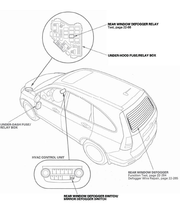
- UNDER-DASH FUSE/ RELAY BOX
- UNDER-HOOD FUSE/RELAY BOX
- REAR WINDOW DEFOGGER RELAY
- HVAC CONTROL UNIT
- REAR WINDOW DEFOGGER SWITCH/ MIRROR DEFOGGER SWITCH
- REAR WINDOW DEFOGGER
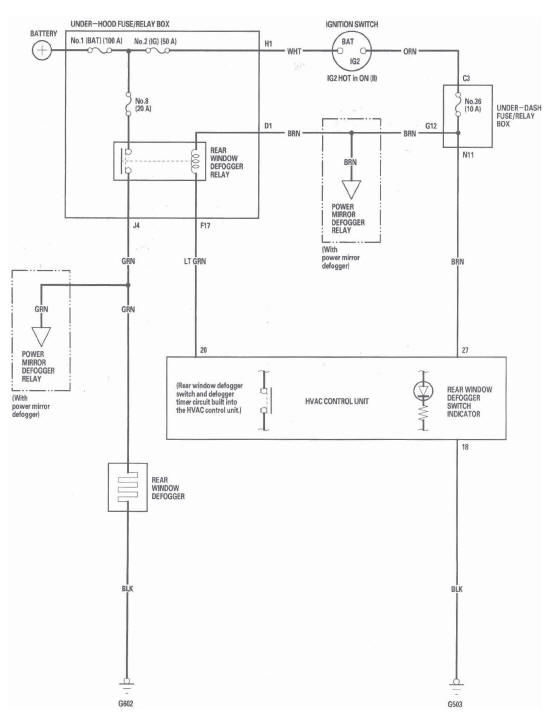
Circuit Diagram
Function Test
NOTE:
- Be careful not to scratch or damage the defogger wires with the tester probe.
- Before testing, check the No.8 (20 A) fuse in the under-hood fuse/relay box and the No. 36 (10 A) fuse in the under-dash fuse/relay box.
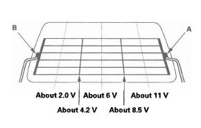
1. Measure voltage between the positive terminal (A) and body ground with the ignition switch and the defogger switch ON.
There should be battery voltage.
- If there is no voltage, check for:
- Faulty rear window defogger relay.
- Faulty HVAC control unit.
- An open in the GRN wire to the positive terminal.
- If there is voltage, go to step 2.
2. Turn the ignition switch OFF, and disconnect the negative terminal (B) from the rear window defogger.
3. Check for continuity between the negative terminal (B) and body ground.
If there is no continuity, check for an open in the wire or poor ground (G602). If there is continuity, go to step 4.
4. Reconnect the negative terminal to the rear window defogger.
5. Turn the ignition switch ON (II) and the rear window defogger switch ON.
6. Touch the voltmeter positive probe to each point on each defogger wire, and the negative probe to the negative terminal.
- If the voltage is as specified, the defogger wire up to that point is OK.
- If the voltage is not as specified, repair the defogger wire.
- If it is more than specified at one of the points, there is a break in the negative half of the wire.
- If it is less than specified at one of the points, there is a break in the positive half of the wire.
Defogger Wire Repair
NOTE: To make an effective repair, the broken section must be no longer than 1 in. (25 mm).
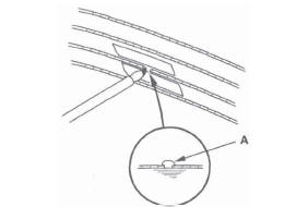
1. Lightly rub the area around the broken section (A) with fine steel wool, then clean it with alcohol.
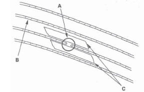
2. Carefully mask above and below the broken portion of the defogger wire (B) with cellophane tape (C).
3. Using a small brush, apply a heavy coat of silver conductive paint (commercially available) (A) extending about 1/8" on both sides of the break.
Allow 25 minutes to dry.
4. Do the function test to confirm that the wire is repaired.
5. Apply a second coat of paint in the same way. Let it dry 3 hours before removing the tape.
READ NEXT:
 Immobilizer System
Component Location Index
IMMOBILIZER INDICATOR
IMMOBILIZER-KEYLESS CONTROL UNIT (Built-in receiver)
UNDER-DASH
FUSE/RELAY BOX
IMOES UNIT
(Built into the MICU)
PCM
IGNITION KEY
TRANSPONDE
Audio System
Component Location Index
LEFT REAR DOOR SPEAKER
AUDIO REMOTE SWITCH (Except LX model)
LEFT TWEETER (Except LX model)
DRIVER'S DOOR SPEAKER
AUDIO UNIT
NAVIGATION UNIT
RIGHT TWEETER
(Except LX
SEE MORE:
Driving Guidelines
Your vehicle has higher ground
clearance that allows you to travel
over bumps, obstacles, and rough
terrain. It also provides good
visibility so you can anticipate
problems earlier.
Because your vehicle rides higher
off the ground, it has a high center
of gravity that can cause it to
Tire Labeling
The tires that came on your vehicle
have a number of markings. Those
you should be aware of are described
below.
Tire Size
Whenever tires are replaced, they
should be replaced with tires of the
same size. Below is an example of
tire size with an explanation of what
each component m
