Honda CR-V: MICU Input Test
1. Before testing, troubleshoot the B-CAN System Diagnosis Test Mode A, and check the No.8 (10 A), No. 10 (7.5 A), and No. 38 (30 A) fuses in the under-dash fuse/relay box.
2. Disconnect under-dash fuse/relay box connectors E, F, S, and T.
NOTE: All connector views are wire side of female terminals.
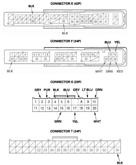
3. Inspect the connector and socket terminals to be sure they are all making good contact.
- If the terminals are bent, loose or corroded, repair them as necessary and recheck the system.
- If the terminals look OK, go to step 4.
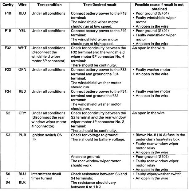
4. With the connectors still disconnected, make these input tests at the appropriate connector.
- If any test indicates a problem, find and correct the cause, then recheck the system.
- If all the input tests prove OK, go to step 5.
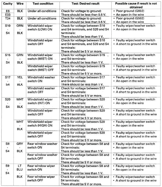
5. Reconnect the connectors to the under-dash fuse/relay box, and make these input tests at the connectors.
- If any test indicates a problem, find and correct the cause, then recheck the system.
- If all the input tests prove OK, the MICU must be faulty; replace the under-dash fuse/relay box.
READ NEXT:
 Wiper/Washer Switch Test/Replacement
1. Remove the steering column covers.
2. Disconnect the dashboard wire harness 8P
connector (A) from the wiper/washer switch (B).
3. Remove the two screws, then slide out the wiper/
washer switch.
Gauges
Component Location Index
GAUGE CONTROL MODULE
Self-diagnostic Function
Input Test
Rewriting the ODO Data and Transferring Smart
Maintenance on a New Gauge Control Module
Replacement
Out
Reminder Systems
Component Location Index
GAUGE CONTROL MODULE
MICU
Circuit Diagram
Control Unit Input Test
NOTE: Before testing, troubleshoot the B-CAN System Diagnosis Test Mode A.
MICU
1. Turn the ignition s
SEE MORE:
No sound is heard from speaker(s) (display is
normal) (with navigation)
NOTE:
Set the fader and balance positions to the center.
Before doing symptom troubleshooting, do the
power switch will not turn ON troubleshooting.
1. Check that the volume button is not set to the MIN
level.
Is it at MIN level? YES-Raise the volume level, and recheck the function.
NO-Go to
Loading Discs in the In-dash Disc Changer
Your vehicle’s in-dash disc changer
holds up to six discs.
1. Press the LOAD button until you
hear a beep and see ‘‘LOAD’’ on
the display.
To load only one CD, press and
release the LOAD button.
2. The disc number for an empty
position is highlighted and the red
disc load in
© 2016-2026 Copyright www.hcrv.net
