Honda CR-V: Reminder Systems
Component Location Index
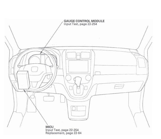
- GAUGE CONTROL MODULE
- MICU
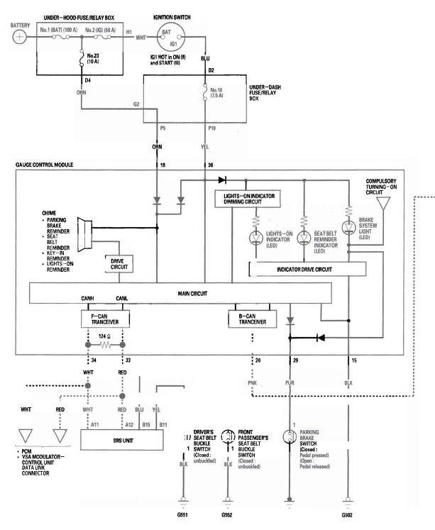
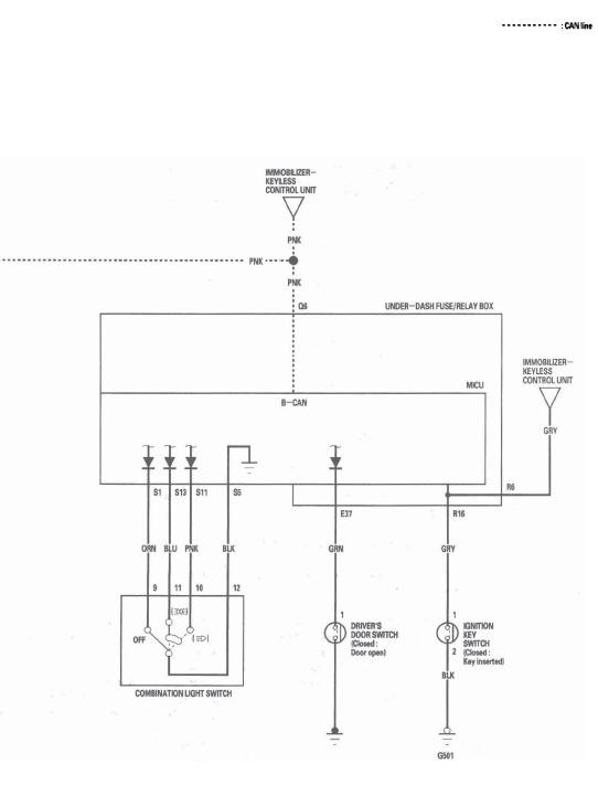
Circuit Diagram
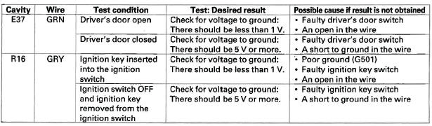
Control Unit Input Test
NOTE: Before testing, troubleshoot the B-CAN System Diagnosis Test Mode A.
MICU
1. Turn the ignition switch OFF.
2. Remove the left kick panel.
3. Disconnect the under-dash fuse/relay box connectors.
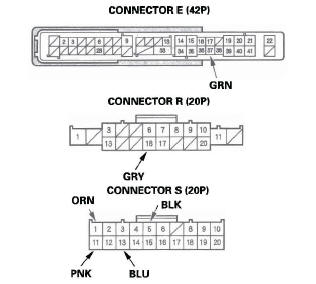
NOTE: All connector views are wire side of female terminals.
4. Inspect the connector and socket terminals to be sure they are all making good contact.
- If the terminals are bent, loose or corroded, repair them as necessary, and recheck the system.
- If the terminals are OK, go to step 5.
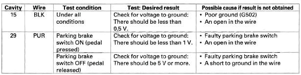
5. Reconnect the connectors, then make these input tests at the connector.
- If any test indicates a problem, find and correct the cause, then recheck the system.
- If all the input tests prove OK, go to step 6.
Gauge Control Module
6. Turn the ignition switch OFF.
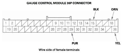
7. Remove the gauge control module.
8. Disconnect the gauge control module 36P connector.
9. Inspect the connector and socket terminals to be sure they are all making good contact.
- If the terminals are bent, loose or corroded, repair them as necessary, and recheck the system.
- If the terminals are OK, go to step 10.
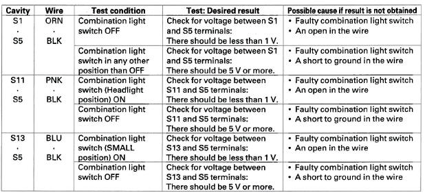
10. With the connectors still disconnected, make these input tests at all connectors.
- If any test indicates a problem, find and correct the cause, then recheck. the system.
- If the input tests prove OK, go to step 11.
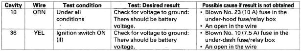
11. Reconnect the gauge control module 36P connector, then make these input tests at the connector.
- If any test indicates a problem, find and correct the cause, then recheck the system.
- If all the input tests prove OK, go to step 12.
12. Do the Gauge Self-diagnostic Function Procedure.
- If the beeper sounds and the seat belt reminder light flashes, go to step 13.
- If the beeper does not sound or the seat belt reminder light does not flash, replace the gauge control module.
13. Substitute a known-good gauge control module, and recheck the system.
- If the symptom is gone, the gauge control module is faulty; replace it.
- If the symptom is still present, the MICU is faulty; replace the under-dash fuse/relay box.
READ NEXT:
 Moonroof
Component Location Index
MOON ROOF SWITCH
MOON ROOF CONTROL UNIT/MOTOR
Resetting the Moonroof Control Unit
Resetting the moon roof is required when any of the following have occurred:
The moonr
Accessory Power Sockets
Component Location Index
CONSOLE ACCESSORY
POWER SOCKET RELAY
CONSOLE ACCESSORY POWER SOCKET
FRONT ACCESSORY POWER SOCKET
UNDER-DASH
FUSE/RELAY BOX
FRONT ACCESSORY
POWER SOCKET RELAY
CARGO
Power Mirrors
Component Location Index
POWER MIRRORS/POWER MIRROR DEFOGGERS
AUXILIARY
UNDER-HOOD
RELAY BOX
POWER MIRROR
DEFOGGER RELAY
REAR WINDOW DEFOGGER SWITCH/
MIRROR DEFOGGER SWITCH
POWER MIRROR
SEE MORE:
Installing a Child Seat with LATCH
Your vehicle is equipped with
LATCH (Lower Anchors and
Tethers for CHildren) at the rear
seats to secure a child seat in any
seating position: one in each outer
seating position, or one in the center.
The five lower anchors are located
between the seat-back and seat
bottom, and are to
Power Windows
Turn the ignition switch to the ON
(II) position to raise or lower any
window. To open the window, push
the switch down and hold it. Release
the switch when you want to stop the
window. To close the window, pull
back on the switch and hold it.
The windows will operate for up to
10
