Honda CR-V: Power Mirrors
Component Location Index
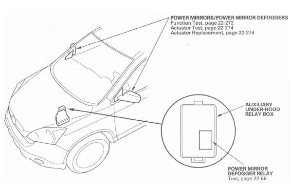
- POWER MIRRORS/POWER MIRROR DEFOGGERS
- AUXILIARY UNDER-HOOD RELAY BOX
- POWER MIRROR DEFOGGER RELAY
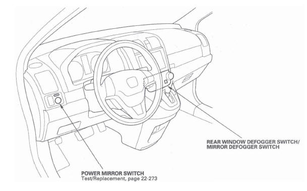
- REAR WINDOW DEFOGGER SWITCH/ MIRROR DEFOGGER SWITCH
- POWER MIRROR SWITCH
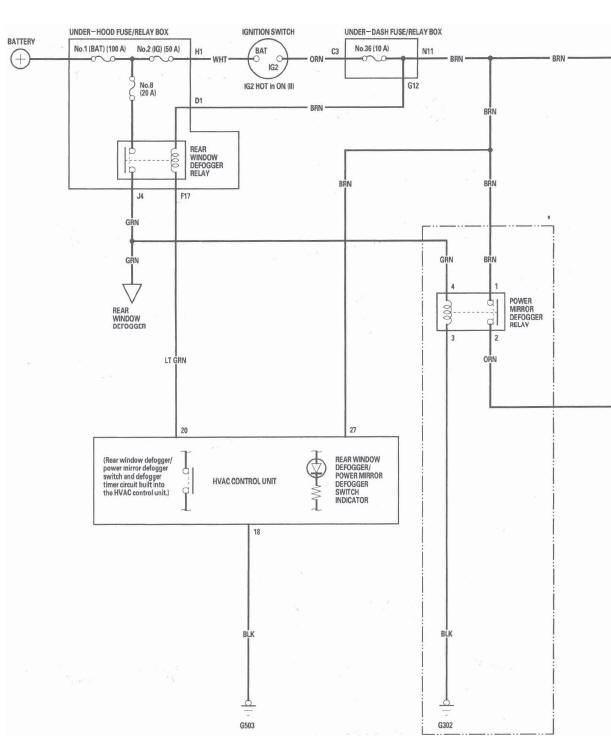
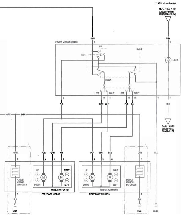
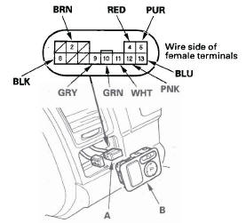
Circuit Diagram
Function Test
1. Remove the power mirror switch.
2. Disconnect the 13P connector (A) from the power mirror switch (B).
3. Choose the appropriate test based on the symptom:
- Both mirrors don't work, go to step 4.
- Left mirror doesn't work, go to step 6.
- Right mirror doesn't work, go to step 7.
- Mirror defoggers don't work, go to step 8.
Both mirrors
4. Check for voltage between the No.2 terminal and body ground with the ignition switch ON (II).
There should be battery voltage.
- If there is no battery voltage, check for:
- Blown No. 36 (10 A) fuse in the under-dash fuse/relay box.
-
An open in the BRN wire.
- If there is battery voltage, go to step 5.
5. Check for continuity between the No.6 terminal and body ground.
There should be continuity.
- If there is no continuity, check for:
- An open in the BLK wire.
- Poor ground (G501).
- If there is continuity, check both mirrors individually.
Left mirror
6. Connect the No.2 and No. 10 terminals, and the No.5 (or No. 12) and No.6 terminals with jumper wires.
The left mirror should tilt down (or swing left) with the ignition switch ON (II).
- If the left mirror does not tilt down (or does not
swing left), check for an open in the PUR (or PNK)
wire between the left mirror and the 13P
connector.
If the wire is OK, check the left mirror actuator.
- If the mirror neither tilts down nor swings left, repair the GRN wire.
- If the mirror works properly, check the mirror switch.
Right mirror
7. Connect the No. 2 and No. 11 terminals, and the No.5 (or No. 13) and No.6 terminals with jumper wires. The right mirror should tilt down (or swing left) with the ignition switch ON (II).
- If the mirror does not tilt down (or does not swing
left), check for an open in the PUR (or BLU) wire
between the right mirror and the 13P connector.
If the wire is OK, check the right mirror actuator.
- If the mirror neither tilts down nor swings left, repair the WHT wire.
- If the mirror works properly, check the mirror switch.
Defogger
8. Connect the power mirror defogger relay No.1 and No.2 terminals with a jumper wire, and check for voltage between the No.1 terminal of the mirror connectors and body ground. There should be battery voltage and both mirrors should warm up with the ignition switch ON (II).
- If there is no voltage or neither warms up, check
for:
- An open in the ORN wire.
- Blown No. 36 (10 A) fuse in the under-dash fuse/relay box.
- If only one fails to warm up, check:
- Its defogger.
- Poor ground (G501, G503).
- If both warm up, check the defogger switch or the power mirror defogger relay.
Power Mirror Switch Test/Replacement
1. Remove the driver's dashboard lower cover.
2. Push the driver's switch panel (A) out from the dashboard, and disconnect the connectors (B).
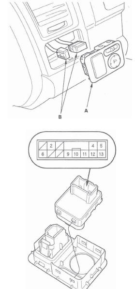
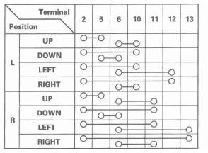
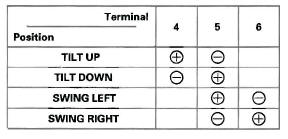
3. Check for continuity between the terminals in each switch position according to the table.
4. If the continuity is not as specified, replace the switch.
5. Install the switch in the reverse order of removal.
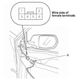
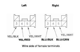
Power Mirror Actuator Test
1. Remove the door panel.
2. Disconnect the 6P connector (A) from the power mirror actuator.
3. Check actuator operation by connecting power and ground according to the table.
4. If the mirror fails to work properly, replace the power mirror actuator.
Defogger Test
5. Check for continuity between the power mirror actuator 6P connector NO.1 and No.2 terminals.
There should be continuity. If there is no continuity, check for an open in the wire between the mirror actuator 6P connector and the mirror holder terminals. If the wire harness is OK, replace the mirror holder.
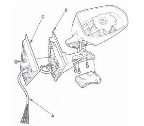
Power Mirror Actuator Replacement
Removal
1. Remove the mirror holder.
2. Remove the power mirror, and disconnect the power mirror 6P connector from the door wire harness.
3. Record the power mirror 6P connector (A) terminal locations and wire colors.
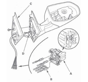
4. Disassemble the power mirror 6P connector, and remove all terminals (B) from the connector.
5. Remove the screw and the gasket (C).
6. Remove the screw and the harness clip (D).
7. Remove the cover (A).
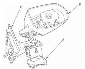
8. Remove the three screws, and separate the mirror housing (B) from the bracket (C).
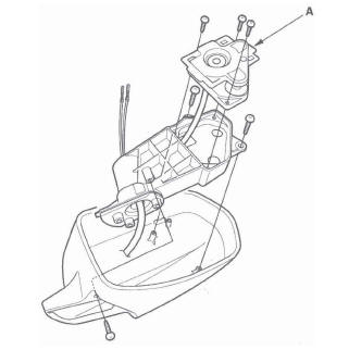
9. Remove the screws and the actuator (A).
Installation
1. Route the wire harness (A) of a new actuator through the hole in the bracket (B) and gasket (C).
2. Install the parts in the reverse order of removal.
3. Insert the new actuator terminals into the connector in the original arrangement.
4. Apply tape to seal the intersection of the wire harness and the gasket.
5. Reassemble in the reverse order of disassembly.
NOTE: Be careful not to break the mirror when reinstalling it to the actuator.
6. Reinstall the mirror assembly on the door.
7. Operate the power mirror to ensure smooth operation.
READ NEXT:
 Seat Heaters
Component Location Index
DRIVER'S SEAT
HEATER RELAY (HIGH)
DRIVER'S SEAT
HEATER RELAY (LOW)
DRIVER'S SEAT CUSHION HEATER
DRIVER'S SEAT-BACK HEATER
FRONT PASSENGER'S
SEAT-BACK HEATER
FRONT
Rear Window Defogger
Component Location Index
UNDER-DASH FUSE/
RELAY BOX
UNDER-HOOD FUSE/RELAY BOX
REAR WINDOW DEFOGGER RELAY
HVAC CONTROL UNIT
REAR WINDOW DEFOGGER SWITCH/
MIRROR DEFOGGER SWITCH
REAR WINDOW DEF
Immobilizer System
Component Location Index
IMMOBILIZER INDICATOR
IMMOBILIZER-KEYLESS CONTROL UNIT (Built-in receiver)
UNDER-DASH
FUSE/RELAY BOX
IMOES UNIT
(Built into the MICU)
PCM
IGNITION KEY
TRANSPONDE
SEE MORE:
Connecting a USB Flash Memory Device
1. Open the upper glove box.
2. Push the release button to release
the USB adapter cable.
3. Connect the USB flash memory
device to the USB connector
correctly and securely.
When the USB flash memory device
is connected, the USB indicator is
shown in the display.
System Description
Outline
The rear differential has a real-time 4WD control mechanism that enables 4WD
by transmitting appropriate driving
force from the front wheels to the rear wheels when necessary. It uses a
real-time 4WD dual pump system (DPS) with
a light and compact cam mechanism, and integrates the drive co
