Honda CR-V: Accessory Power Sockets
Component Location Index
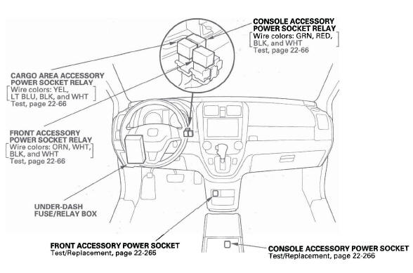
- CONSOLE ACCESSORY POWER SOCKET RELAY
- CONSOLE ACCESSORY POWER SOCKET
- FRONT ACCESSORY POWER SOCKET
- UNDER-DASH FUSE/RELAY BOX
- FRONT ACCESSORY POWER SOCKET RELAY
- CARGO AREA ACCESSORY POWER SOCKET RELAY
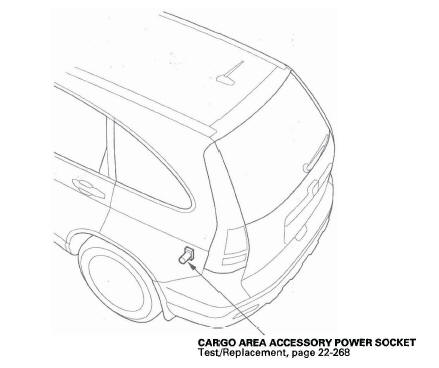
- CARGO AREA ACCESSORY POWER SOCKET
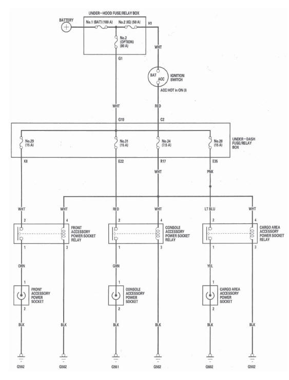
Circuit Diagram
Front Accessory Power Socket Test/Replacement
NOTE: If all of the front, console, and cargo area accessory power sockets do not work, check the No. 34 (7.5 A) fuse in the under-dash fuse/relay box and ground (G502).
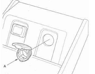
1. Remove the dashboard center lower cover.
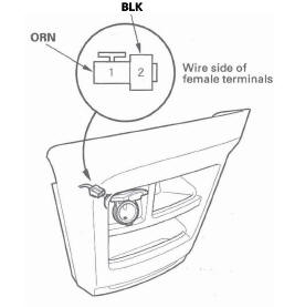
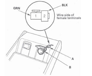
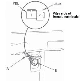
2. Disconnect the 2P connector (A) from the front accessory power socket (B).
3. Inspect the connector terminals to be sure they are all making good contact.
- If the terminals are bent, loose, or corroded, repair them as necessary and recheck the system.
- If the terminals look OK, go to step 4.
4. Turn the ignition switch to ACC (I).
5. Measure voltage between the power accessory socket 2P connector No.1 terminal and body ground. There should be battery voltage.
- If there is battery voltage, go to step 6.
- If there is no battery voltage, check for:
- Blown No. 29 (15 A) fuse in the under-dash fuse/relay box.
- Faulty front accessory power socket relay.
- Poor ground (G502).
- An open in the wire.
6. Check for continuity between the No.2 terminal and body ground. There should be continuity.
- If there is continuity, go to step 7.
- If there is no continuity, check for:
- Poor ground (G502).
- An open in the wire.
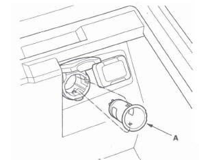
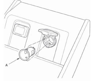
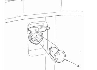
7. Remove the socket (A).
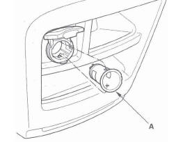
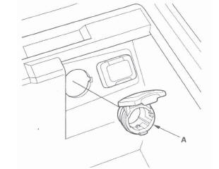
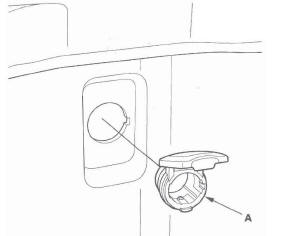
8. Remove the housing (A) from the panel.
9. Install the power socket in the reverse order of removal.
Console Accessory Power Socket Test/Replacement
NOTE: If all of the front, console, and cargo area accessory power sockets do not work, check the No. 34 (7.5 A) fuse in the under-dash fuse/relay box and poor ground (G502).
1. For EX-L: Remove the center console.
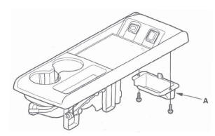
For EX: Remove the center table AUX cover (A) from the table.
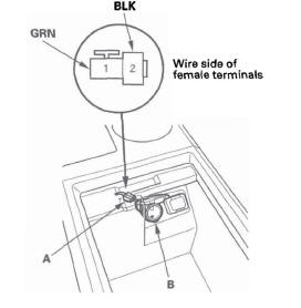
2. Disconnect the 2P connector (A) from the console accessory power socket (B).
EX-L
EX
3. Inspect the connector terminals to be sure they are all making good contact.
- If the terminals are bent, loose, or corroded, repair them as necessary and recheck the system.
- If the terminals look OK, go to step 4.
4. Turn the ignition switch to ACC (I).
5. Measure voltage between the No.1 terminal and body ground. There should be battery voltage.
- If there is battery voltage, go to step 6.
- If there is no battery voltage, check for:
- Blown No. 31 (15 A) fuse in the under-dash fuse/relay box.
- Faulty console accessory power socket relay.
- Poor ground (G502).
- An open in the wire.
6. Check for continuity between the No.2 terminal and body ground. There should be continuity.
- If there is continuity, go to step 7.
- If there is no continuity, check for:
- Poor ground (G551).
- An open in the wire.
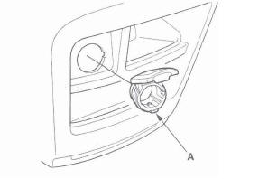
7. Remove the socket (A).
EX-L
EX
8. Remove the housing (A).
EX-L
EX
9. Install the power socket in the reverse order of removal.
Cargo Area Accessory Power Socket Test/Replacement
NOTE: If all of the front, console, and cargo area accessory power sockets do not work, check the No. 34 (7.5 A) fuse in the under-dash fuse/relay box and ground (G502).
1. Remove the rear side trim panel.
2. Disconnect the 2P connector (A) from the cargo area accessory power socket (B).
3. Inspect the connector terminals to be sure they are all making good contact.
- If the terminals are bent, loose, or corroded, repair them as necessary and recheck the system.
- If the terminals look OK, go to step 4.
4. Turn the ignition switch to ACC (I).
5. Measure voltage between the No.1 terminal and body ground. There should be battery voltage.
- If there is battery voltage, go to step 5.
- If there is no battery voltage, check for:
- Blown No. 28 (15 A) fuse in the under-dash fuse/relay box.
- Faulty cargo area accessory power socket relay.
- Poor ground (G502).
- An open in the wire.
6. Check for continuity between the No.2 terminal and body ground. There should be continuity.
- If there is continuity, go to step 7.
- If there is no continuity, check for:
- Poor ground (G602).
- An open in the wire.
7. Remove the socket (A).
8. Remove the housing (A) from the panel.
9. Install the power socket in the reverse order of removal.
READ NEXT:
 Power Mirrors
Component Location Index
POWER MIRRORS/POWER MIRROR DEFOGGERS
AUXILIARY
UNDER-HOOD
RELAY BOX
POWER MIRROR
DEFOGGER RELAY
REAR WINDOW DEFOGGER SWITCH/
MIRROR DEFOGGER SWITCH
POWER MIRROR
Seat Heaters
Component Location Index
DRIVER'S SEAT
HEATER RELAY (HIGH)
DRIVER'S SEAT
HEATER RELAY (LOW)
DRIVER'S SEAT CUSHION HEATER
DRIVER'S SEAT-BACK HEATER
FRONT PASSENGER'S
SEAT-BACK HEATER
FRONT
Rear Window Defogger
Component Location Index
UNDER-DASH FUSE/
RELAY BOX
UNDER-HOOD FUSE/RELAY BOX
REAR WINDOW DEFOGGER RELAY
HVAC CONTROL UNIT
REAR WINDOW DEFOGGER SWITCH/
MIRROR DEFOGGER SWITCH
REAR WINDOW DEF
SEE MORE:
Shafts and Clutches
Mainshaft Disassembly, Inspection, and Reassembly
1. Inspect the thrust needle bearing and the needle bearing for galling and
rough movement.
2. Inspect the splines for excessive wear and damage.
3. Check shaft bearing surface for scoring and excessive wear.
4. Before installing the O-rings, wra
Fasten and Position the Seat Belts
Insert the latch plate into the buckle,
then tug on the belt to make sure the
belt is securely latched. Check that
the belt is not twisted, because a
twisted belt can cause serious
injuries in a crash.
The seat belt in the center position
of the back seat can be unlatched
and retracte
