Honda CR-V: Gauges
Component Location Index
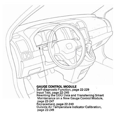
- GAUGE CONTROL MODULE
- Self-diagnostic Function
- Input Test
- Rewriting the ODO Data and Transferring Smart Maintenance on a New Gauge Control Module
- Replacement
- Outside Air Temperature Indicator Calibration
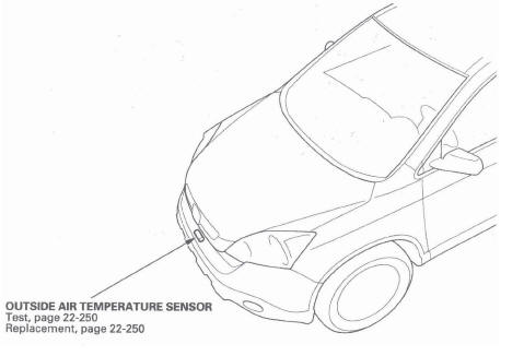
- OUTSIDE AIR TEMPERATURE SENSOR
- Test
- Replacement
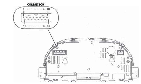
- CONNECTOR
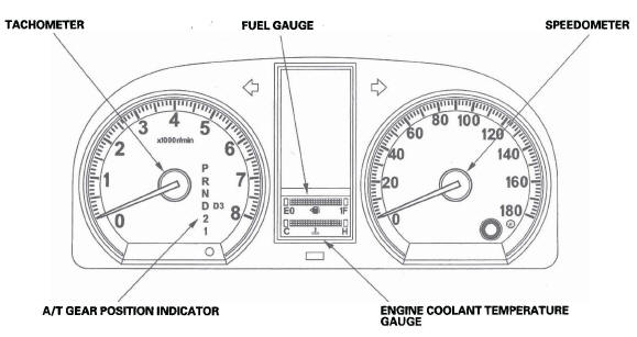
- TACHOMETER
- FUEL GAUGE
- SPEEDOMETER
- A/T GEAR POSITION INDICATOR
- ENGINE COOLANT TEMPERATURE GAUGE
Self-diagnostic Function
Before checking the gauge system, refer to the B-CAN System Diagnosis Test Mode A.
The gauge control module has the self-diagnostic functions shown, and also has the customizable reset function.
- The beeper drive circuit check.
- The indicator drive circuit check.
- The switch input test.
- The LCD segments check.
- The gauges drive circuit check (speedometer, tachometer, fuel gauge, coolant temperature gauge).
- The communication line check of the body-controller area network (B-CAN) communication line and the fast-controller area network (F-CAN) communication line.
NOTE: Indicators are also controlled via the communication line.
Entering the self-diagnostic function with the HDS
Using the HDS, select Body Electrical, Gauges, then Function Test, and do the self-diagnostic function.
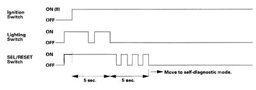
Entering the self-diagnostic function (manual method)
NOTE: This procedure takes precise timimg. It may take several tries to enter the self-diagnosis mode.
Before doing the self-diagnostic function, check the No. 10 (7.5 A) fuse in the under-dash fuse/relay box and the No. 23 (10 A) fuse in the under-hood fuse/relay box.
1. Push and hold the SEL/RESET switch button.
2. Turn the headlights ON.
3. Turn the ignition switch ON (II).
4. Within 5 sec., turn the headlights OFF, then ON and OFF again.
5. Within 5 sec., release the SEL/RESET switch button, and then push and release the button three times repeatedly.
NOTE:
- While in the self-diagnostic mode, the dash lights brightness controller operates normally.
- While in the self-diagnostic mode, the SEL/RESET button is used to start the Beeper Drive Circuit Test and the Gauge Drive Circuit Check.
The Indicator Drive Circuit Check
When entering the self-diagnostic mode, the following indicators blink: ABS indicator, A/T gear position indicator, brake system indicator, charging system indicator, cruise control indicator, cruise indicator, door indicator, DRL indicator, high beam indicator, immobilizer indicator, lights-on indicator, low tire pressure indicator, low fuel indicator, malfunction indicator lamp (MIL), maintenance required indicator, oil pressure indicator, seat belt indicator, security indicator, side airbag cutoff indicator, SRS indicator, tailgate indicator, TPMS indicator, VSA indicator, VSA activation indicator, and washer fluid level indicator (Canada models).
Switch Input Check
At the initial stage of the self-diagnostic function, the beep sounds intermittently, the beeper sounds continuously when any of the following switch inputs are switched from OFF to ON: Cruise control main, SET, RESUME, CANCEL switches, SEL/RESET switch, parking brake switch, and VSA OFF switch.
The illumination volume (+) and (-) switch (dash lights brightness controller) can be tested by turning on the headlights and verifying that the dash lights brightness changes as you turn the switch from full dim to full bright.
The Beeper Drive Circuit Check
When entering the self-diagnostic mode, the beeper sounds five times.
The LCD Segment Check
When entering the self-diagnostic mode, all the segments blink five times. After that, all segments come on.
The Gauge Drive Circuit Check
When entering the self-diagnostic mode, the speedometer and tachometer needles sweep from the minimum position to maximum position, then returns to the minimum position.
NOTE:
After the beeper stops sounding and the gauge needle returns to the minimum position, pushing the SEL/RESET switch starts the Beeper Drive Circuit Check (one beep) and the
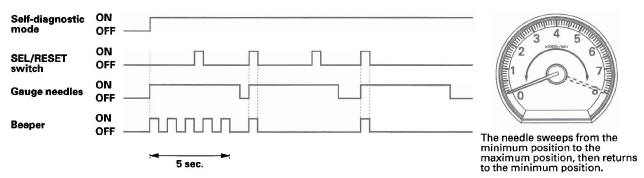
If the needle fails to sweep, or the beeper does not sound, replace the gauge control module.
The Communication Line Check
While in the self-diagnostic mode, the Communication Line Check starts after the LCD Segments Check.
If all segments come on, the communication line is OK. If faulty, the word "Error" will be indicated on the odometer display followed by number(s).
Error Code List

Example Indication
Normal (all segments come on.):

Faulty (Error 1):

- If the word "Error 1" is indicated, there is a malfunction in the
communication line between the gauge control
module and the fast-controller area network (F-CAN). Check for DTCs in the
PCM and troubleshoot any DTCs found.
If no DTCs are found, go to indicated troubleshooting.
- If the word "Error 2" is indicated, there is a malfunction in the communication line between the gauge control module and the body-controller area network (S-CAN). Go to indicated troubleshooting.
If any F-CAN or B-CAN communication line errors are found, go to DTC check using HDS.
Ending the self-diagnostic function
Turn the ignition switch OFF.
NOTE: If the vehicle speed exceeds 1.2 mph (2 km/h), the self-diagnostic function ends.
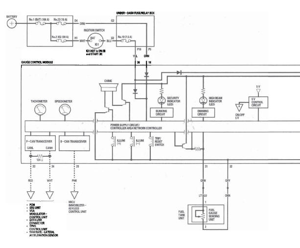
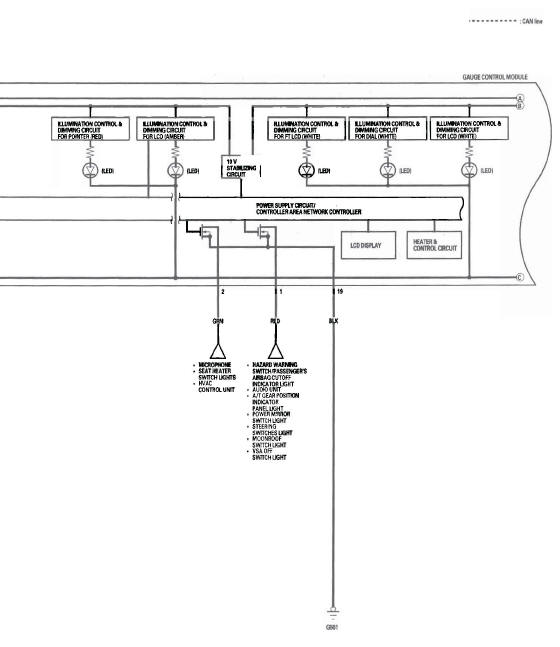
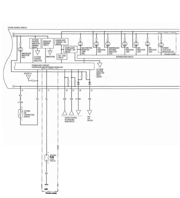
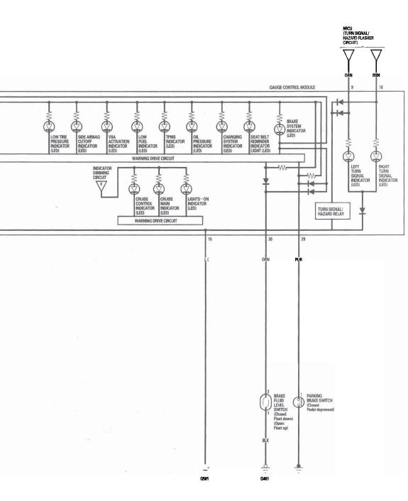
Circuit Diagram
DTC Troubleshooting
DTC B1152: Gauge Control Module Internal Error (EEPROM)
1. Clear the DTCs with the HDS.
2. Turn the ignition switch OFF, and then back ON (II).
3. Wait for 6 seconds or more.
4. Check for DTCs with the HDS.
Is DTC B1152 indicated? YES-Replace the gauge control module.
NO-Intermittent failure, the system is OK at this time. Check the battery condition, and the charging system.
DTC B1155: Gauge Control Module Lost Communication with the MICU (HLSW Message)
DTC B1156: Gauge Control Module Lost Communication with the MICU (WIPSW Message)
DTC B1157: Gauge Control Module Lost Communication with the MICU (MICU Message)
DTC B1159: Gauge Control Module Lost Communication with the MICU (DOORSW Message)
DTC B1160: Gauge Control Module Lost Communication with the MICU (DRLOCKSW Message)
DTC B1188: Gauge Control Module Lost Communication with the MICU (RM Message)
NOTE: If you are troubleshooting multipule DTCs, be sure to follow the instructions in B-CAN System Diagnosis Test Mode A.
1. Clear the DTCs with the HDS.
2. Turn the ignition switch OFF, and then back ON (II).
3. Wait for 6 seconds or more.
4. Check for DTCs with the HDS.
Is DTC B1155,B1156,B1157,B1159,B1160, or B1188 indicated? YES-Go to step 5.
NO-Intermittent failure, the system is OK at this time. Check for loose or poor connections between the gauge control module and the MICU.
5. Check for DTCs with the HDS.
Is DTC B1155,B1156,B1157,B1159,B1160, or B1188 indicated with DTCs B1905? YES-Faulty MICU; replace the under-dash fuse/relay box.
NO-Replace the gauge control module.
DTC B1168: Gauge Control Module Lost Communication with the PCM (ENG Message)
DTC B1169: Gauge Control Module Lost Communication with the PCM (A/T Messages)
NOTE: If you are troubleshooting multipule DTCs, be sure to follow the instructions in B-CAN System Diagnosis Test Mode A.
1. Clear the DTCs with the HDS.
2. Turn the ignition switch OFF, and then back ON (II).
3. Wait for 6 seconds or more.
4. Check for DTCs with the HDS.
Is DTC B1168 or B1169 indicated? YES-Go to step 5.
NO-Intermittent failure, the system is OK at this time. Check for loose or poor connections.
5. Check for Fuel and Emission system DTCs with the HDS.
Is any DTCs indicated? YES-Go to the indicated DTCs, then recheck.
NO-Go to step 6.
6. Turn the ignition switch OFF.
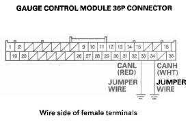
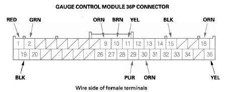
7. Disconnect the gauge control module 36P connector.
8. Jump the SCS with the HDS.
9. Disconnect the PCM connector A (44P).
10. Connect the gauge control module 36P connector No. 33 and No. 34 terminals and body ground with jumper wires.
11. Check for continuity between the PCM connector A (44P) No. 36 and No. 37 terminals and body ground individually.
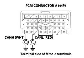
Is there less than 3 Ω ? YES-Update the PCM if it does not have the latest software (see page 11-7), or substitute a known-good PCM (see page 11-8), and recheck. If the indication goes away, replace the original PCM (see page 11-219). If the DTC is still present, replace the gauge control module.
NO-Repair an open in the wire.
DTC B1170: Gauge Control Module Lost Communication with the VSA Modulator-Control Unit (VSA message)
NOTE: If you are troubleshooting multiple DTCs, be sure to follow the instructions in B-CAN System Diagnosis Test Mode A.
1. Clear the DTCs with the HDS.
2. Turn the ignition switch OFF, and then back ON (II).
3. Wait for 6 seconds or more.
4. Check for DTCs with the HDS.
Is DTC B1170 indicated? YES-Go to step 5.
NO-Intermittent failure, the system is OK at this time. Check for loose or poor connections between the gauge control module and the VSA modulator-control unit.
5. Check for VSA system DTCs with the HDS.
Is any DTCs indicated? YES-Go to the indicated DTCs, then recheck.
NO-Go to step 6.
6. Turn the ignition switch OFF.
7. Disconnect the gauge control module 36P connector.
8. Disconnect the VSA modulator-control unit 46P connector.
9. Connect the gauge control module 36P connector No. 33 and No. 34 terminals and body ground with jumper wires.
10. Check for continuity between the VSA modulator control unit 46P connector No. 38 and No. 39 terminals and body ground individually.
Is there less than 3 Ω ? YES-Substitute a known-good VSA modulator-control unit, and recheck. If the indication goes away, replace the original VSA modulator-control unit. If the DTC is still present, replace the gauge control module.
NO-Repair an open in the wire.
DTC B1173: Gauge Control Module Lost Communication with the TPMS Control Unit (TPMS message)
NOTE: If you are troubleshooting multiple DTCs, be sure to follow the instructions in B-CAN System Diagnosis Test Mode A.
1. Clear the DTCs with the HDS.
2. Turn the ignition switch OFF, and then back ON (II).
3. Wait for 6 seconds or more.
4. Check for DTCs with the HDS.
Is DTC B1173 indicated? YES-Go to step 5.
NO-Intermittent failure, the system is OK at this time. Check for loose or poor connections.
5. Check for TPMS DTCs with the HDS.
Is any DTCs indicated? YES-Go to the indicated DTCs, then recheck.
NO-Go to step 6.
6. Turn the ignition switch OFF.
7. Disconnect the gauge control module 36P connector.
8. Disconnect the TPMS control unit 20P connector.
9. Check for continuity between the gauge control module 36P connector No. 33 and No. 34 terminals and the TPMS control unit 20P connector No.1 and No. 11 terminals respectively.
Is there continuity? YES-Substitute a known-good TPMS control unit, and recheck. If the indication goes away, replace the original TPMS control unit. If the DTC is still present, replace the gauge control module.
NO-Repair an open in the wire.
DTC B1175: Fuel Level Sensor (Fuel Gauge Sending Unit) Circuit Open
NOTE: If you are troubleshooting multiple DTCs, be sure to follow the instructions in B-CAN System Diagnosis Test Mode A.
1. Clear the DTCs with the HDS.
2. Turn the ignition switch OFF, and then back ON (II).
3. Wait for 30 seconds.
4. Check for DTCs with the HDS.
Is DTC B1175 indicated? YES-Go to step 5.
NO-Intermittent failure, the fuel level sensor circuit is OK at this time. Check for loose or poor connections.
5. Turn the ignition switch OFF.
6. Disconnect the fuel tank unit 4P connector and the gauge control module 36P connector.
7. Connect the fuel tank unit 4P connector No.1 and No.3 terminals and body ground with jumper wires.
8. Check for continuity between gauge control module 36P connector No. 31 and No. 32 terminals and body ground individually.
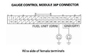
Is there continuity? YES-Go to step 9.
NO-Repair an open in the wire between the gauge control module and the fuel tank unit.
9. Do the fuel gauge sending unit test.
Is the fuel gauge sending unit OK? YES-Replace the gauge control module.
NO-Replace the fuel tank unit.
DTC B1176: Fuel Level Sensor (Fuel Gauge Sending Unit) Circuit Short
NOTE: If you are troubleshooting multiple DTCs, be sure to follow the instructions in B-CAN System Diagnosis Test Mode A.
1. Clear the DTCs with the HDS.
2. Turn the ignition switch OFF, and then back ON (II).
3. Wait for 30 seconds.
4. Check for DTCs with the HDS.
Is DTC B1176 indicated? YES-Go to step 5.
NO-Intermittent failure, the fuel level sensor circuit is OK at this time. Check for worn/missing insulation or an internal short in the wire.
5. Turn the ignition switch OFF.
6. Disconnect the fuel tank unit 4P connector.
7. Clear the DTCs with the HDS.
8. Turn the ignition switch OFF, and then back ON (II).
9. Wait for 30 seconds.
10. Check for DTCs with the HDS.
Is DTC B1176 indicated? YES-Go to step 11.
NO-Replace the fuel gauge sending unit.
11. Disconnect the gauge control module 36P connector.
12. Check for continuity between the gauge control module 36P connector No. 31 terminal and body ground.
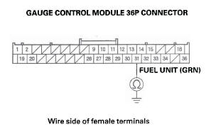
Is there continuity? YES-Repair a short in the wire between the gauge control module and the fuel tank unit.
NO-Replace the gauge control module.
DTC B1177: Battery Voltage Abnormal
NOTE: If you are troubleshooting multiple DTCs, be sure to follow the instructions in B-CAN System Diagnosis Test Mode A.
1. Clear the DTCs with the HDS.
2. Turn the ignition switch OFF, and then back ON (II).
3. Check for DTCs with the HDS.
Is DTC B1177 indicated? YES-Go to step 8.
NO-Go to step 4.
4. Clear the DTCs with the HDS.
5. Turn the ignition switch OFF, and then back ON (II).
6. Crank the engine.
7. Check for DTCs with the HDS.
Is DTC B1177 indicated? YES-Go to step 8.
NO-Intermittent failure, the gauge control module and power supply voltage (lG1) that is supplied to the gauge control module are OK at this time. The battery may have been discharged, and recovered.
8. Check the battery and the charging system.
Is the battery condition normal and the charging system OK? YES-Go to step 9.
NO-The battery needs a recharge or replacement, or the charging system needs to be repaired.
9. Turn the ignition switch ON (II).
10. With the gauge control module 36P connector still connected, measure voltage between the body ground and the gauge control module 36P connector No. 36 terminal.
Is there battery voltage? YES-Replace the gauge control module.
NO-Repair an open or high resistance in the wire between the ignition switch and the gauge control module.
DTC B1178: F-CAN Communication Line Error
NOTE: If you are troubleshooting multiple DTCs, be sure to follow the instructions in B-CAN System Diagnosis Test Mode A.
1. Clear the DTCs with the HDS.
2. Turn the ignition switch OFF, and then back ON (II).
3. Wait for 6 seconds or more.
4. Check for DTCs with the HDS.
Is DTCs B1168, B1169, B1170, and/or B1187 indicated? YES-Go to the indicated DTCs troubleshooting.
NO-Intermittent failure, the system is OK at this time. Check for open or short in the wire.
DTC B1187: Gauge Control Module Lost Communication with the SRS Unit (SRS Message)
NOTE: If you are troubleshooting multiple DTCs, be sure to follow the instructions in B-CAN System Diagnosis Test Mode A.
1. Clear the DTCs with the HDS.
2. Turn the ignition switch OFF, and then back ON (II).
3. Wait for 6 seconds or more.
4. Check for DTCs with the HDS.
Is DTC B1187 indicated? YES-Go to step 5.
NO-Intermittent failure, the system is OK at this time. Check for loose or poor connections between the gauge control module and the SRS unit.
5. Check for SRS DTCs with the HDS.
Is any DTCs indicated? YES-Go to the indicated DTCs troubleshooting, then recheck.
NO-Go to step 6.
6. Turn the ignition switch OFF.
7. Disconnect the gauge control module 36P connector.
8. Disconnect the SRS unit connector A (28P).
9. Check for continuity between the gauge control module 36P connector No. 33 and No. 34 terminals and the SRS unit connector A (28P) No. 12 and No. 11 terminals respectively.
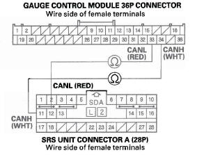
Is there continuity? YES-Substitute a known-good SRS unit, and recheck. If the indication goes away, replace the original SRS unit. If the DTC is still present, replace the gauge control module.
NO-Repair an open in the wire.
Gauge Control Module Input Test
NOTE: Before testing, do the gauge control module self-diagnosis procedure, and make sure the B-CAN communication line is OK.
1. Turn the ignition switch OFF.
2. Remove the gauge control module, and disconnect the 36P connector from it.
3. Inspect the connector and socket terminals to be sure they are all making good contact.
- If the terminals are bent, loose or corroded, repair them as necessary, and recheck the system.
- If the terminals are OK, go to step 4.
4. With the connector still disconnected, make these input tests at the connector.
- If any test indicates a problem, find and correct the cause, then recheck the system.
- If all the input tests prove OK, go to step 5.
5. Reconnect the connector to the gauge control module, and make the input tests at the connector.
- If any test indicates a problem, find and correct the cause, then recheck the system.
- If the input test proves OK, the gauge control module must be faulty; replace it.
Rewriting the ODO Data and Transferring Smart Maintenance on a New Gauge Control Module
NOTE:
- Obtain a new gauge control module before starting the rewriting process.
- Rewriting is not possible on a gauge control module that will not communicate with the HDS.
- Make sure that the HDS shows the correct VIN for the vehicle you are working on.
- Once you have started this procedure, you must complete it before removing the HDS from the DLC.
- Connect a battery jumper box (not a battery charger) to insure that correct battery voltage will be maintained.
1. Before replacing the gauge control module, connect the HDS.
2. Select GAUGES from the BODY ELECTRICAL system select menu with the HDS.
3. Select "Gauge Control Module Replacement (ODO Rewrite)" from the ADJUSTMENT menu, and follow the instructions on the display to retrieve the ODO value and the Smart Maintenance Information.
4. Replace the gauge control module.
5. Follow the instructions on the display to write the new ODO value and Smart Maintenance to the new gauge control module. If the data transfer fails, refer to the instructions below to release the locked ODO value.
Release Locked odometer mileage to the original gauge control module.
If, after you attempt to transfer mileage, the odometer display has dashes (---), is garbled, or shows an incorrect value, the original gauge control module needs to be unlocked and restored to its original state: 1. Confirm that you have the latest HDS version of software.
2. Make sure that the HDS shows the correct VIN for the vehicle you are working on.
3. With the ignition switch OFF, reconnect the original gauge control module.
4. Completely re-boot the HDS.
5. Clear any stored DTCs.
6. Navigate to Body Electric/Gauges/Adjustment! Instrument Panel Replacement.
7. Select "3. Releasing Locked ODO Value."
8. Follow the prompts and the Odometer mileage will be restored.
9. Start over and make sure the screen prompts are followed.
Gauge Control Module Replacement
1. Remove the instrument panel.
2. Remove the three screws from the gauge control module (A).
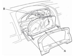
3. Disconnect the 36P connector (B) from the gauge control module.
4. Install the gauge in the reverse order of removal.
Outside Air Temperature Indicator Calibration
Description
The outside temperature sensor is located behind the center of the front bumper. The gauge control module uses measurements from this sensor to display the outside air temperature.
Because of the location of the sensor, it may be affected by heat, reflection from the road, engine and radiator heat or hot exhaust from surrounding traffic.
These conditions can heat soak the outside air temperature sensor and cause inaccurate readings.
Logic has been written into the gauge control module to help prevent abnormal of fluctuating outside air temperature indicator readings.
Outside Air Temperature Indicator Logic
Initial outside air temperature indication after the ignition switch is turned ON (II).
- If the engine coolant temperature is 140ºF (60 ºC) or higher when the ignition switch is turned ON (II), the outside air temperature will be indicated the last reading before the key was turned off regardless of the current temperature measured by the outside air temperature sensor.
- If the engine coolant temperature is 139ºF (59 ºC) or lower when the ignition switch is turned ON (II), the current temperature measured by the outside air temperature sensor will be indicated.
Update to the outside air temperature indicator while driving
If the temperature measured by the outside air temperature sensor is greater than the temperature on the outside air temperature indicator, the outside temperature indicator will increase by 1 ºF (1 ºC) per minute after the vehicle speed is greater than 19 mph (30 km/h) for more than 1 minute and 30 seconds. It will continue to increase until the current outside air temperature is indicated. So, the first change to the outside air temperature indicator is 1 minute and 30 seconds after the vehicle speed is greater than 19 mph (30 km/h). lf the vehicle speed drops below 19 mph (30 km/h), the indicator will not update again until the vehicle speed is increased to 19 mph (30 km/h) or more for more than 1 minute and 30 seconds again.
If the outside air temperature is less than 140 ºF (60 ºC), the temperature increases 1 ºF (1 ºC) every 2 seconds until the current outside air temperature.
If the outside air temperature is less than the indicated temperature, the temperature will decrease 1 ºF (1 ºC) every 2 seconds until the current outside air temperature is indicated regardless of vehicle speed.
Troubleshooting
If the indicator displays "---" for more than 2 seconds after selecting the outside air temperature display mode, check the climate control system or multiplex integrated control system for DTCs (see B-CAN System Diagnosis Test Mode A).
Calibration
The outside air temperature indicator's displayed temperature can be recalibrated +-5ºF or +-3 ºC to meet the customer's expectations.
Calibrate the outside air temperature with the HDS.
Outside Air Temperature Sensor Test
1. Remove the outside air temperature sensor.
2. Dip the sensor in ice water, and measure the resistance. Then pour warm water on the sensor, and check for a change in resistance.
3. Compare the resistance reading between the No.1 and No.2 terminals of the outside air temperature sensor with the specifications shown in the graph; the resistance should be within the specifications.
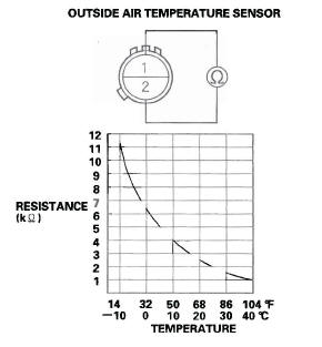
4. If the resistance is not as specified, replace the outside air temperature sensor.
Outside Air Temperature Sensor Replacement
1. Disconnect the 2P connector (A) from the outside air temperature sensor (B).
2. Lift the tab (C) to release the lock, then remove the outside air temperature sensor from the front bumper.
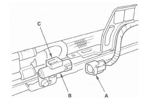
3. Install the sensor in the reverse order of removal.
READ NEXT:
 Reminder Systems
Component Location Index
GAUGE CONTROL MODULE
MICU
Circuit Diagram
Control Unit Input Test
NOTE: Before testing, troubleshoot the B-CAN System Diagnosis Test Mode A.
MICU
1. Turn the ignition s
Moonroof
Component Location Index
MOON ROOF SWITCH
MOON ROOF CONTROL UNIT/MOTOR
Resetting the Moonroof Control Unit
Resetting the moon roof is required when any of the following have occurred:
The moonr
Accessory Power Sockets
Component Location Index
CONSOLE ACCESSORY
POWER SOCKET RELAY
CONSOLE ACCESSORY POWER SOCKET
FRONT ACCESSORY POWER SOCKET
UNDER-DASH
FUSE/RELAY BOX
FRONT ACCESSORY
POWER SOCKET RELAY
CARGO
SEE MORE:
Improving Fuel Economy
Vehicle Maintenance
A properly maintained vehicle
maximizes fuel economy. Poor
maintenance can significantly reduce
fuel economy. Always maintain your
vehicle according to the maintenance
messages displayed on the multiinformation display.
For example:
Use the recommended viscosity
mo
Fuel Recommendation
Your vehicle is designed to operate
on unleaded gasoline with a pump
octane number of 87 or higher. Use
of a lower octane gasoline can cause
a persistent, heavy metallic rapping
noise that can lead to engine damage.
We recommended using a quality
gasoline containing detergent
additive
