Honda CR-V: MICU Input Test
NOTE:
- The MICU turns on the headlights (high beams) in a dim mode for the
daytime running lights under the following
conditions:
- The ignition switch is ON (II)
- The headlight switch is OFF
- The parking brake is released (parking brake switch OFF)
- If the vehicle is equipped with an optional remote control engine start system (Canada), the daytime running lights will not function when started with the remote start.
1. Before testing, troubleshoot the B-CAN System Diagnosis Test Mode A.
2. Check the No. 12 (10 A), No. 13 (10 A), No. 15 (7.5 A), No. 16 (10 A), No. 17 (10 A), No. 18 (20 A), No. 19 (15 A), No. 21 (30 A), and No. 37 (7.5 A) fuses in the under-dash fuse/relay box. If any fuse is blown, replace it and go to step 3.
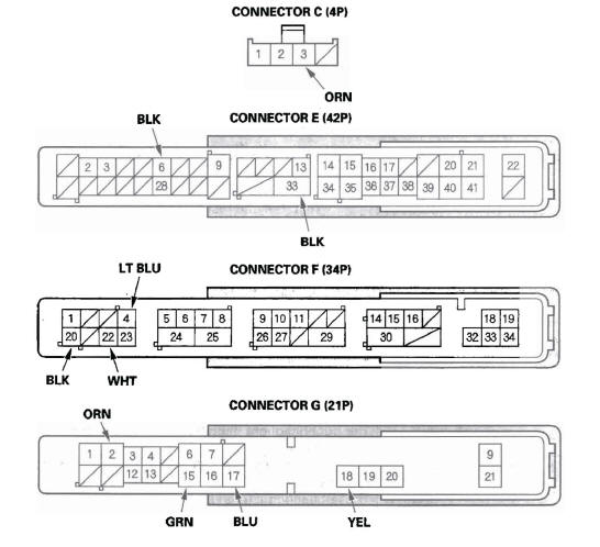
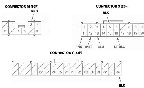
3. Disconnect the under-dash fuse/relay box connectors E, F, G, M, S, and T.
NOTE: All connector views are wire side of female terminals.
4. Inspect the connector and socket terminals to be sure they are all making good contact.
- If the terminals are bent, loose or corroded, repair them as necessary and recheck the system.
- If the terminals look OK, go to step 5.
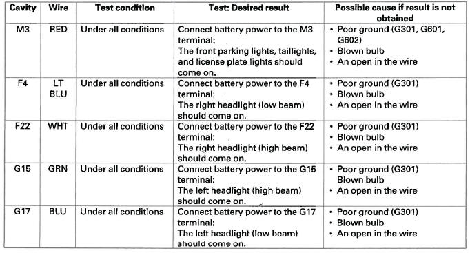
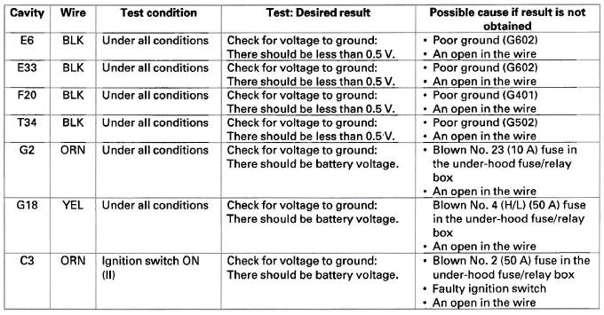
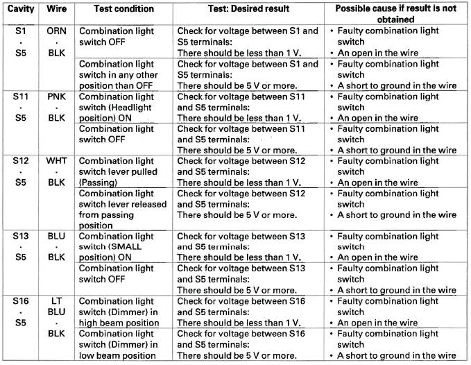
5. With the connectors still disconnected, make these input tests at the appropriate connector.
- If any test indicates a problem, find and correct the cause, then recheck the system.
- If all the input tests prove OK, go to step 6.
6. Reconnect the connectors, and do these input tests at the connectors.
- If any test indicates a problem, find and correct the cause, then recheck the system.
- If all the input tests prove OK, the MICU is faulty; replace the under-dash fuse/relay box.
Combination Light Switch Test/Replacement
1. Remove the dashboard lower cover.
2. Remove the steering column covers.
3. Disconnect the 12P connector (A) from the combination light switch (B).
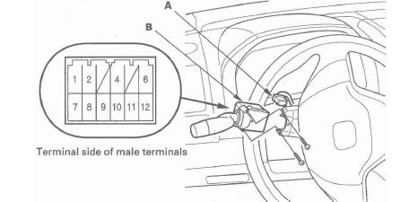
4. Remove the two screws, then slide out the combination light switch.
5. Inspect the connector terminals to be sure they are all making good contact.
- If the terminals are bent, loose or corroded, repair them as necessary, and recheck the system.
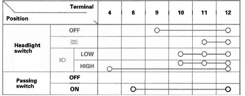
- If the terminals look OK, check for continuity between the terminals in each switch position according to the tables.
Light switch
Turn signal switch
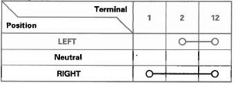
6. If the continuity is not as specified, replace the switch.
READ NEXT:
 Headlight Adjustment
CAUTION
Headlights become very hot during use; do not
touch them or any attaching hardware immediately
after they have been turned off.
Before adjusting the headlights:
Park the vehicle on a level s
Turn Signal/Hazard Flasher
Component Location Index
TURN SIGNAL SWITCH
(Built into the combination light switch)
TURN SIGNAL INDICATORS
HAZARD WARNING SWITCH
MICU (Built into the under-dash fuse/relay box)
Circuit Diagr
Interior Lights
Component Location Index
With moon roof
INDIVIDUAL MAP LIGHTS
INTERIOR LIGHT SWITCH
(Built into the moonroof switch)
AMBIENT LIGHT
(Built into the moonroof switch)
CEILING LIGHT
CARGO AREA LI
SEE MORE:
Replacing a High-mount Brake Light Bulb
1. Open the tailgate.
Unlatch the top of the cover by
pulling back on it with your hands.
2. Place a cloth on the side edge of
the cover to prevent scratches.
Remove the cover by carefully
prying on the edge with a small
flat-tip screwdriver and pulling the
cover off.
3. Remove the
Cylinder Head Cover Removal/Installation
Cylinder Head Cover Removal
1. Remove the intake manifold cover.
2. Remove the four ignition coils.
3. Disconnect the evaporative emission (EVAP)
canister purge valve connector.
4. Remove the dipstick (A), the breather hose (B), and
power steering (P/S) hose clamp (C).
5. Remove two bolts (D) se
