Honda CR-V: Master Cylinder
Master Cylinder Replacement
NOTICE
- Do not spill brake flu id on the vehicle; it may damage the paint; if brake fluid gets on the paint, wash it off immediately with water.
- Be careful not to damage or deform the brake lines during removal and installation.
- To prevent the brake fluid from flowing, plug and cover the hose ends and joints with a shop towel or equivalent.
1. Remove the air cleaner housing cover.
2. Remove the reservoir cap, then remove brake fluid from the master cylinder reservoir with a syringe.
3. Disconnect the brake fluid level switch connector (A).
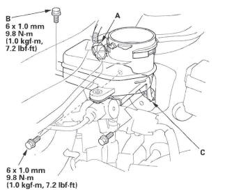
4. Remove the reservoir mounting bolt (B), then remove reservoir bracket (C).
5. Disconnect the brake lines (A) from the master cylinder (B). To prevent spills, cover the hose joints with rags or shop towels.
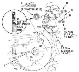
6. Remove the master cylinder mounting nuts (C) and washers (D).
7. Remove the master cylinder from the brake booster (E). Be careful not to bend or damage the brake lines when removing the master cylinder.
8. Remove the rod seal (F) from the master cylinder.
NOTE: During installation, set the new rod seal onto the master cylinder with its grooved side (G) toward the master cylinder.
9. Install in the reverse order of removal, and note these items:
- Coat the inner bore lip and outer circumference of the new rod seal with the Shin-Etsu silicone grease (P/N 08798-9013).
- Check the brake pedal height and free play after installing the master cylinder, and adjust if necessary.
10. Bleed the brake system.
11. Spin the wheels to check for brake drag.
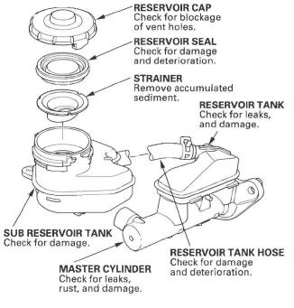
Master Cylinder Inspection
1. Inspect and note these items:
- Before reassembling, check that all parts are free of dirt and other foreign particles.
- Do not try to disassemble the master cylinder assembly. Replace the master cylinder assembly with a new part if necessary.
- Do not allow dirt or foreign matter to contaminate the brake fluid.
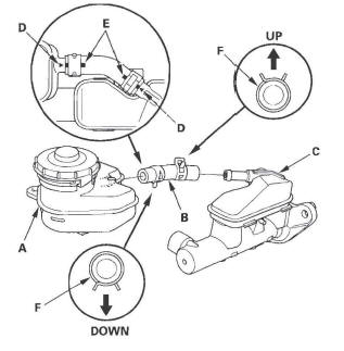
2. If the reservoir tank hose was disconnected, install the subreservoir tank (A) and the reservoir tank hose (B) to the reservoir tank (C).
NOTE:
- Align the raised arrows (D) on the subreservoir tank and reservoir tank with the paint marks (E) on the hose.
- Position the direction of the clamps (F).
READ NEXT:
 Brake Booster
Brake Booster Test
Functional Test
1. With the engine stopped, press the brake pedal several times to deplete
the vacuum reservoir, then press the brake pedal hard, and hold it for 15
seconds. If th
Rear Brake
Rear Brake Pad Inspection and Replacement
Special Tools Required
Brake caliper piston compressor 07AAE-SEPA101
CAUTION
Frequent inhalation of brake pad dust, regardless of material
composition, could
Parking Brake
Parking Brake Inspection
CAUTION
Frequent inhalation of brake pad dust, regardless of material
composition, could be hazardous to your health.
Avoid breathing dust particles.
Never use an air ho
SEE MORE:
Sound Quality Diagnosis
Special Tools Required
Diagnostics CD 07AAZ-SDBA100
Use the following tests to check sound quality.
NOTE: Before beginning the following tests, write down
the customer's bass, treble, fader and balance settings,
and then set them to their center positions for testing.
Left/Right Channel 10
Do this
Introduction
Congratulations! Your selection of a 2010 Honda CR-V was a wise
investment. It will give you years of driving pleasure.
One of the best ways to enhance the enjoyment of your new vehicle is to
read this manual. In it, you will learn how to operate its driving controls and
convenience items. Af
