Honda CR-V: Parking Brake
Parking Brake Inspection
CAUTION
Frequent inhalation of brake pad dust, regardless of material composition, could be hazardous to your health.
- Avoid breathing dust particles.
- Never use an air hose or brush to clean brake assemblies. Use an OSHA-approved vacuum cleaner.
1. Raise the rear of the vehicle, and support it with safety stands in the proper locations.
2. Remove the rear wheels.
3. Release the parking brake, and remove the rear brake disc/drum.
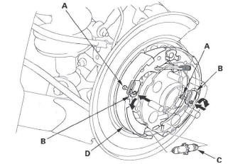
4. Check the parking brake linings (A) for cracking, glazing, wear, and contamination.
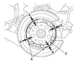
5. Measure the parking brake lining thickness (B).
Measurement does not include brake shoe thickness.
Parking brake lining thickness:
Standard: 1.7-3.0 mm (0.067-0.118 in.)
Service limit: 1.0 mm (0.04 in.)
6. If the parking brake lining thickness is less than the service limit, replace all the parking brake shoes as a set.
7. Check the hub (C) for smooth operation. If it requires servicing replace the hub bearing unit.
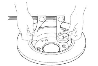
8. Measure the inside diameter of the parking brake drum with inside vernier calipers.
Parking brake drum inside diameter:
Standard: 199.9-200.0 mm (7.870-7.874 in.)
Service limit: 201.0 mm (7.913 in.)
9. If the inside diameter of the parking brake drum is more than service limit, replace the brake disc/drum.
10. Check the parking brake disc/drum for scoring, grooves, and cracks.
11. Clean the mating surface of the brake disc/drum and the inside of the wheel, then install the rear wheels.
Parking Brake Shoe Replacement
CAUTION
Frequent inhalation of brake pad dust, regardless of material composition, could be hazardous to your health.
- Avoid breathing dust particles.
- Never use an air hose or brush to clean brake assemblies. Use an OSHA-approved vacuum cleaner.
Disassembly
1. Raise the rear of the vehicle, and support it with safety stands in the proper locations.
2. Remove the rear wheels.
3. Release the parking brake, and remove the rear brake caliper and brake disc/drum.
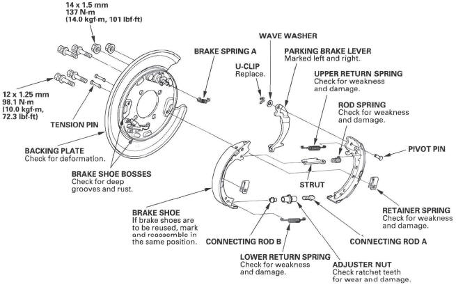
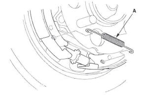
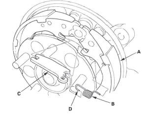
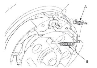
4. Disconnect and remove brake spring A and the upper return spring (B).
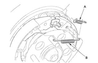
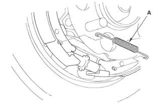
5. Disconnect and remove the lower return spring (A).
6. Remove the tension pins (A) by pushing the respective retainer springs (B) and turning the pin.
7. Remove the adjuster assembly (C) by moving forward brake shoe (D).
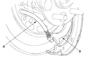
8. Remove the rearward brake shoe by disconnecting the parking brake cable (A) from the parking brake lever (B).
9. Disconnect the rod spring (A), and remove the strut (B).
10. Remove the parking brake shoes (C).
11. Remove the U-clip (A), wave washer (B), parking brake lever (C), and pivot pin (D) from the brake shoe (E).
Reassembly
1. Apply Molykote 44MA grease to the sliding surface of the pivot pin (A), and insert the pin into the rearward brake shoe (B) from the outside.
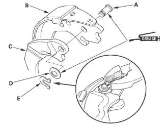
2. Install the parking brake lever (C) and wave washer (D) on the pivot pin, and secure with a new U-clip (E).
- Install the wave washer with its convex side facing out.
- Pinch the U-clip securely to prevent the parking brake lever from coming off the brake shoe.
3. Position the parking brake shoes (A), then hook the rod spring (B) on the strut (C) first with the spring end (D) pointing downward. Then hook the rod spring to the parking brake shoe, and install the strut on the parking brake shoes.
4. Apply a thin coat of Molykote 44MA grease to the brake shoe ends and strut ends (A), the sliding surfaces of the parking brake shoe (B), and the pivot of the parking brake lever (C) as shown. Wipe off any excess. Keep grease off the brake linings.
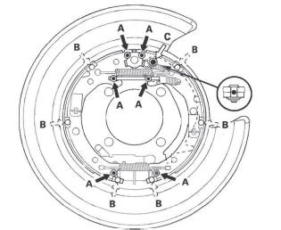
Greasing symbols:
 Brake
shoe ends and strut ends
Brake
shoe ends and strut ends
 Sliding
surface of the shoe
Sliding
surface of the shoe
 Pivot
of parking brake lever
Pivot
of parking brake lever
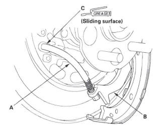
5. Connect the parking brake cable (A) to the parking brake lever (B). Apply silicone grease to the cable contact surface (C) on the backing plate.
6. Install the tension pins (C) and retainer springs (D).
Make sure the tension pin does not contact the parking brake lever.
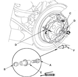
7. Install connecting rods A and B on the adjuster nut (E).
NOTE:
- Clean the threaded portions of connecting rod A and the sliding surface of connecting rod B, then coat them with rubber grease.
- Shorten connecting rod A by fully turning the adjuster nut.
8. Position the brake shoe adjuster assembly (F) on the parking brake shoes.
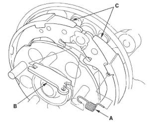
9. Install the lower return spring (A).
10. Install the upper return spring (B) and brake spring A.
11. Install the rear brake disc/drum and rear brake caliper.
12. Do the major parking brake adjustment.
Parking Brake Shoe Lining Break-in
NOTE:
- Do brake lining surface break-in when replacing shoes with new brake linings and/or new rear brake disc/drum.
- Check the number of parking brake lever clicks.
Adjust the parking brake before lining surface break-in.
1. Park the vehicle on a firm, level surface.
2. Release the parking brake pedal.
3. Press the parking brake pedal with 196 N*m (20 kgf, 44 Ibf) (4 clicks) of force.
4. Drive the vehicle for 1/4 mile (400 m) at about 31 mph (50 km /h).
5. Stop the vehicle, and release the parking brake for 5-10 minutes to allow the brake disc/drum to cool.
6. Repeat steps 3 through 5 again.
7. Check the parking brake pedal adjustment.
Brake Pedal Replacement
1. Remove the driver's dashboard undercover.
2. Disconnect the brake pedal position switch connector (A).
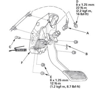
3. Remove the lock pin (B) and joint pin (C).
4. Remove the brake pedal bracket mounting bolt (D) and nuts (E).
5. Remove the brake pedal with bracket (F).
6. Install the brake pedal in the reverse order of removal.
7. Do the brake pedal and brake pedal position switch adjustment.
READ NEXT:
 Brake Hose
Brake Hose and Line Inspection
1. Inspect the brake hoses for damage, deterioration, leaks, interference,
and twisting.
2. Check the brake lines for damage, rusting, and leaks. Also check for bent
VSA (Vehicle Stability Assist) System Components
Component Location Index
VSA MODULATOR-CONTROL UNIT
Removal and Installation
UNDER-HOOD FUSE/RELAY BOX
DATA LINK
CONNECTOR (DLC)
STEERING ANGLE SENSOR
Replacement
VSA OFF SWITCH
General Troubleshooting Information
System Indicator
This system has four indicators:
ABS indicator (A)
Brake system indicator (B)
VSA indicator (C)
VSA activation indicator (D)
When the system detects a problem, it will turn the
SEE MORE:
To Select a Station
You can use any of five methods to
find radio stations on the selected
band: tune, seek, scan, the preset
buttons, and auto select.
TUNE - Use the SEEK button to
tune to a desired frequency. Press
the
button to tune to a higher
frequency, and the button to
tune to a lower frequency
Important Safety Precautions
To eliminate potential hazards, read
the instructions before you begin,
and make sure you have the tools
and skills required.
Make sure your vehicle is parked
on level ground, the parking brake
is set, and the engine is off.
To clean parts, use a commercially
available degreaser or par
