Honda CR-V: Knuckle/Hub Bearing Unit Replacement
Exploded View
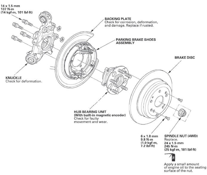
Hub Bearing Unit Replacement
1. Raise the rear of the vehicle, and support it with safety stands in the proper locations.
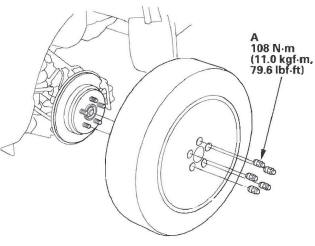
2. Remove the wheel nuts (A) and the rear wheel.
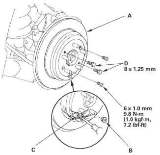
3. Remove the brake hose bracket mounting bolt (A) from the knuckle.
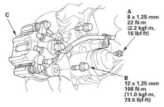
4. Remove the brake caliper bracket mounting bolts (B), and remove the caliper assembly (C) from the knuckle. To prevent damage to the caliper assembly or brake hose, use a short piece of wire to hang the caliper assembly from the undercarriage. Do not twist the brake hose excessively.
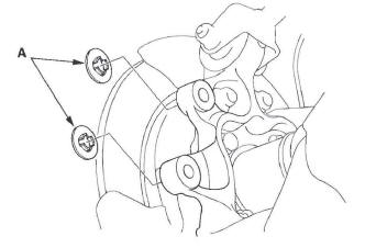
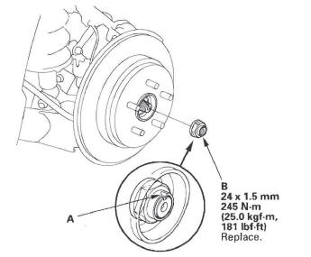
5. Remove the two washers (A).
6. Raise the stake (A), then remove the spindle nut (B).
(4WD only)
7. Release the parking brake, and remove the brake disc/drum (A) from the hub bearing unit.
NOTE:
- Remove the adjuster plug (B), then, if necessary, turn the adjuster bolt (C) with a flat-tip screwdriver until the shoes become loose.
- If the brake drum is stuck to the hub bearing unit,
screw two 8 x 1.25 mm bolts (D) into the brake
drum to push it away from the hub bearing unit.
Turn each bolt 90 degrees at a time to prevent cocking the brake drum.
8. Remove the hub bearing unit (A) from the spindle.
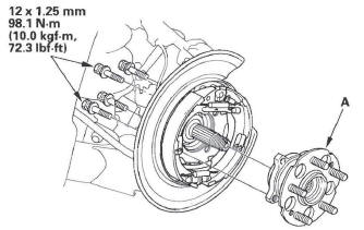
9. Check the hub bearing unit for damage and cracks.
10. Install the hub bearing unit in the reverse order of removal, and note these items:
- Tighten all mounting hardware to the specified torque values.
- Use a new spindle nut during reassembly.
- Before installing the spindle nut, apply a small amount of engine oil to the seating surface of the nut. After tightening, use a drift to stake the spindle nut shoulder against the driveshaft.
- Before installing the brake disc/drum, clean the mating surface of the hub bearing unit and the inside of the brake disc/drum.
- Before installing the wheel, clean the mating surface of the brake disc/drum and the inside of the wheel.
- After installation, press the brake pedal several times to make sure the brakes work.
- Check the wheel alignment, and adjust it if necessary.
Knuckle Replacement
1. Remove the hub bearing unit.
2. Remove the parking brake assembly (A).
NOTE: To prevent damage to the backing plate or parking brake shoes assembly and cable, use a short piece of wire to hang the backing plate from the undercarriage. Do not twist the parking brake cable excessively.
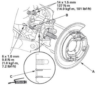
3. Remove the wheel sensor (B). Do not disconnect the wheel sensor connector.
NOTE: During installation, apply multipurpose grease inside of the hole (C) on the knuckle.
4. Place the floor jack under the trailing arm (A), and support the suspension.
NOTE: Do not place the jack against the plate section of the trailing arm.
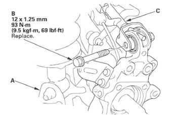
5. Remove the flange bolt (B), and disconnect the upper arm (C) from the knuckle.
NOTE: During installation, install a new flange bolt.
6. Mark the cam positions of the adjusting bolt (A) and adjusting cam (B), then remove the self-locking nut (C), adjusting cam, and adjusting bolt. Discard the self-locking nut.
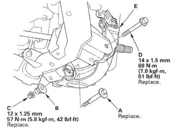
7. Remove the flange bolt (D), and remove the knuckle (E).
NOTE: During installation, install a new flange bolt.
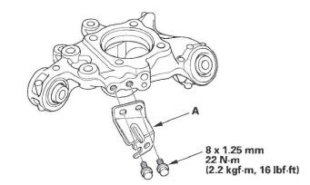
8. Remove the brake hose mounting bracket (A).
9. Install the knuckle in the reverse order of removal, and note these items:
- First install all the suspension components, and lightly tighten bolts and nuts, then place a floor jack under the trailing arm, and raise the suspension to load it with the vehicle's weight before fully tightening bolts and nuts to the specified torque values.
- Tighten all the mounting hardware to the specified torque values.
- Align the cam positions of the adjusting bolt and adjusting cam with the marked positions when tightening.
- Use a new self-locking nut during reassembly.
- Use a new spindle nut during reassembly.
- After tightening the spindle nut, use a drift to stake the spindle nut shoulder against the spindle.
- Before installing the brake disc/drum, clean the mating surface of the hub bearing unit and the inside of the brake disc/drum.
- Before installing the wheel, clean the mating surface of the brake disc/drum and the inside of the wheel.
- Check the wheel alignment, and adjust it if necessary.
READ NEXT:
 Upper Arm Replacement
1. Raise the rear of the vehicle, and support it with safety stands in the
proper locations.
2. Remove the rear wheel.
3. Place a floor jack under the trailing arm, and
support the suspension.
4.
Damper/Spring
Damper/Spring Removal and Installation
Removal
1. Raise the rear of the vehicle, and support it with safety stands in the
proper locations.
2. Remove the rear wheel.
3. Remove the lid (A) on the
TPMS (Tire Pressure Monitoring System)
Component Location Index
TPMS CONTROL UNIT
(Behind the dashboard center lower cover)
Replacement
TIRE PRESSURE SENSOR
Replacement
TIRE PRESSURE SENSOR
Replacement
UNDER-DASH F
SEE MORE:
To Select a Station
You can use any of five methods to
find radio stations on the selected
band: tune, seek, scan, the preset
buttons, and auto select.
TUNE - Use the TUNE bar to tune
the radio to a desired frequency.
Press the
side of the bar to tune
to a higher frequency, and press the
side to tune t
Seat Heaters
If equipped
Both front seats are equipped with
seat heaters. The passenger seat
only has heaters in the seat bottom
because of the side airbag cutoff
system.
The ignition switch must be in the
ON (II) position to use the heaters.
Push the top of the switch, HI, to
rapidly heat
