Honda CR-V: Upper Arm Replacement
1. Raise the rear of the vehicle, and support it with safety stands in the proper locations.
2. Remove the rear wheel.
3. Place a floor jack under the trailing arm, and support the suspension.
4. Remove the wheel sensor harness bracket (A) from the upper arm (B).
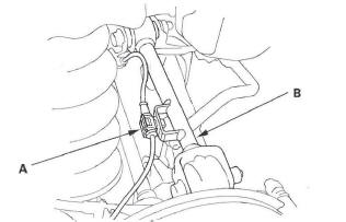
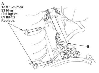
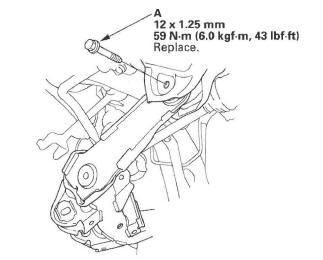
5. Remove the flange bolts (A), and remove the upper arm (B).
NOTE: During installation, install new flange bolts.
6. Install the upper arm in the reverse order of removal, and note these items:
- First install all the suspension components and lightly tighten the bolts and nuts, then place a jack under the trailing arm, and raise the suspension to load it with the vehicle's weight before fully tightening the bolts and nuts to the specified torque values.
- Tighten all the mounting hardware to the specified torque values.
- Before installing the wheel, clean the mating surface of the brake disc/drum and the inside of the wheel.
- Check the wheel alignment, and adjust it if necessary.
Trailing Arm Replacement
1. Raise the rear of the vehicle, and support it with safety stands in the proper locations.
2. Remove the rear wheel.
3. Remove the knuckle.
4. Place the floor jack under the trailing arm (A) to support it.
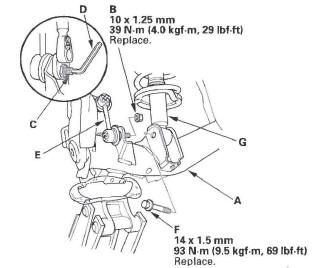
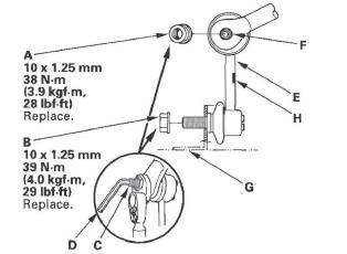
5. Remove the flange nut (B), while holding the joint pin (C) with a hex wrench (D), and disconnect the stabilizer link (E) from the trailing arm.
NOTE: During installation, install a new flange nut.
6. Remove the flange bolt (F), and disconnect the damper (G) from the trailing arm.
7. Remove the trailing arm front mounting bolts (A).
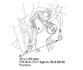
8. Remove the trailing arm rear mounting bolt (A).
9. Lower the jack, and remove the trailing arm.
10. Install the trailing arm in the reverse order of removal, and note these items:
- First install all the suspension components and lightly tighten the bolts and nuts, then place a jack under the trailing arm, and raise the suspension to load it with the vehicle's weight before fully tightening the bolts and nuts to the specified torque values.
- Use new flange bolts during reassembly.
- Tighten all the mounting hardware to the specified torque values.
- Before installing the wheel, clean the mating surface of the brake disc/drum and the inside of the wheel.
- Check the wheel alignment, and adjust it if necessary.
Stabilizer Link Removal/Installation
1. Raise the rear of the vehicle, and support it with safety stands in the proper locations.
2. Remove the rear wheel.
3. Remove the self-locking nut (A) and the flange nut (B) while holding the respective joint pin (C) with a hex wrench (D), then remove the stabilizer link (E).
4. Install the stabilizer link on the stabilizer bar (F) and trailing arm (G) with the joint pins set at the center of their range of movement.
NOTE: The left stabilizer link has a yellow paint mark (H), while the right stabilizer link has a white paint mark.
5. Install a new self-locking nut and a new flange nut, and lightly tighten them.
6. Place the floor jack under the trailing arm, and raise the suspension to load it with the vehicle's weight.
7. Tighten the self-locking nut and the flange nut to the specified torque values while holding the respective joint pin with a hex wrench.
8. Clean the mating surface of the brake disc/drum and the inside of the wheel, then install the rear wheel.
9. Test-drive the vehicle.
10. After 5 minutes of driving, tighten the self-locking nut again to the specified torque value.
Stabilizer Bar Replacement
1. Raise the rear of the vehicle, and support it with safety stands in the proper locations.
2. Remove the rear wheels.
3. Disconnect both stabilizer links from the stabilizer bar.
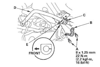
4. Remove the flange bolts (A) and the bushing holders (B), then remove the bushings (C) and the stabilizer bar (D).
5. Install the stabilizer bar in the reverse order of removal, and note these items:
- Note the right and left direction of the stabilizer bar.
- Align the paint marks (E) on the stabilizer bar with the sides of the bushings.
- Note the fore/aft direction of the bushing.
- Refer to the stabilizer link removal/installation to connect the stabilizer bar to the links.
- Clean the mating surface of the brake disc/drum and the inside of the wheel, then install the rear wheel.
- Check the wheel alignment, and adjust it if necessary.
READ NEXT:
 Damper/Spring
Damper/Spring Removal and Installation
Removal
1. Raise the rear of the vehicle, and support it with safety stands in the
proper locations.
2. Remove the rear wheel.
3. Remove the lid (A) on the
TPMS (Tire Pressure Monitoring System)
Component Location Index
TPMS CONTROL UNIT
(Behind the dashboard center lower cover)
Replacement
TIRE PRESSURE SENSOR
Replacement
TIRE PRESSURE SENSOR
Replacement
UNDER-DASH F
General Troubleshooting Information
System Indicator locations
The system has two indicators.
The low pressure indicator (A)
The TPMS indicator (B)
How TPMS Works
The TPMS (tire pressure monitoring system) has a low
pressure indica
SEE MORE:
Towing Equipment and Accessories
Towing can require a variety of
equipment, depending on the size of
your trailer, how it will be used, how
much load you are towing, and
where you tow.
Discuss your needs with your trailer
sales or rental agency, and follow the
guidelines in this section. Also make
sure that all equip
Injector Replacement
1. Relieve fuel pressure.
2. Remove the engine cover.
3. Disconnect the connectors (A) from the injectors.
4. Remove the ground cable bolt (G101) (B).
5. Disconnect the quick-connect fitting (C).
6. Remove the fuel rail mounting nuts (D) from the fuel rail (E).
7. Remove the injector clip (F)
