Honda CR-V: Fan, Fan Motor, Shroud Removal and Installation
Removal
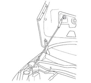
1. Remove the hood support rod, then use it as shown to prop the hood in the wide-open position.
2. Remove the bulkhead cover.
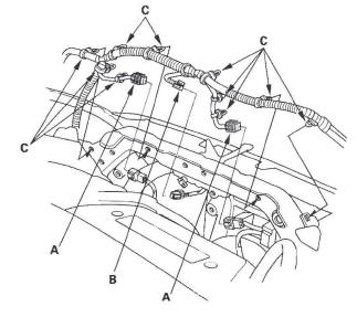
3. Disconnect the fan motor connectors (A) and hood switch connector (B), then remove the harness clips (C).
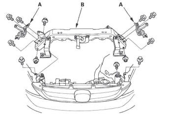
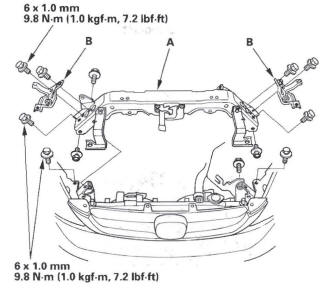
4. Remove the radiator upper brackets (A), then remove the front bulkhead (B).
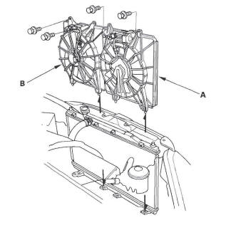
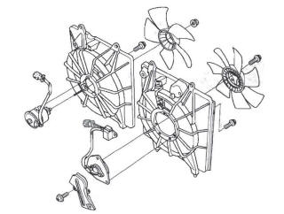
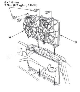
5. Remove the condenser fan shroud assembly (A), then remove the radiator fan shroud assembly (B) from condenser fan shroud side.
6. Disassemble the fan shrouds.
Installation
1. Assemble the fan shrouds.
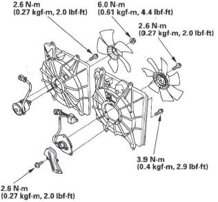
2. Install the radiator fan shroud assembly (A), then install the condenser fan shroud assembly (B).
3. Install the front bulkhead (A), then install the radiator upper brackets (B).
4. Apply body paint to the bulkhead mounting bolts.
5. Connect the fan motor connectors (A) and hood switch connector (B), then install the harness clips (C).

6. Remove the bulkhead cover.
READ NEXT:
 Radiator Replacement
For Japan-produced Model
1. Drain the engine coolant.
2. Remove the hood support rod, then use it as shown
to prop the hood in the wide-open position.
3. Remove the bulkhead cover.
4. Remove the co
Fan Controls
Component Location Index
RADIATOR FAN RELAY
A/C CONDENSER FAN RELAY
FAN CONTROL RELAY
A/C CONDENSER FAN ASSEMBLY
RADIATOR FAN ASSEMBLY
ENGINE COOLANT TEMPERATURE
(ECT) SENSOR 1
E
SEE MORE:
Additional Safety Precautions
Never hold an infant or child on
your lap. If you are not wearing a
seat belt in a crash, you could be
thrown forward and crush the
child against the dashboard or a
seat-back. If you are wearing a
seat belt, the child can be torn
from your arms and be seriously
hurt or killed.
Never
DTC P0116: ECT Sensor 1 Range/Performance Problem
NOTE: Before you troubleshoot, record all freeze data
and any on-board snapshot, and review the general
troubleshooting information.
1. Turn the ignition switch ON (II).
2. Check ECT SENSOR 1 in the DATA LIST with the
HDS.
Is about 176 ºF (80 ºC) or more, or 0.78 V or less
indicated?
YES-Go to s
