Honda CR-V: Fan Controls
Component Location Index
- RADIATOR FAN RELAY
- A/C CONDENSER FAN RELAY
- FAN CONTROL RELAY
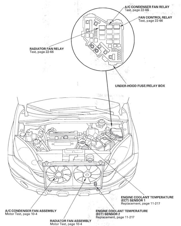
-
A/C CONDENSER FAN ASSEMBLY
-
RADIATOR FAN ASSEMBLY
-
ENGINE COOLANT TEMPERATURE
(ECT) SENSOR 1 -
ENGINE COOLANT TEMPERATURE
(ECT) SENSOR 2
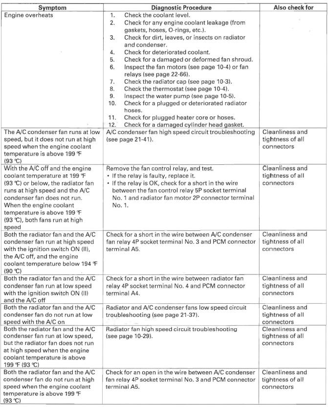
Symptom Troubleshooting Index
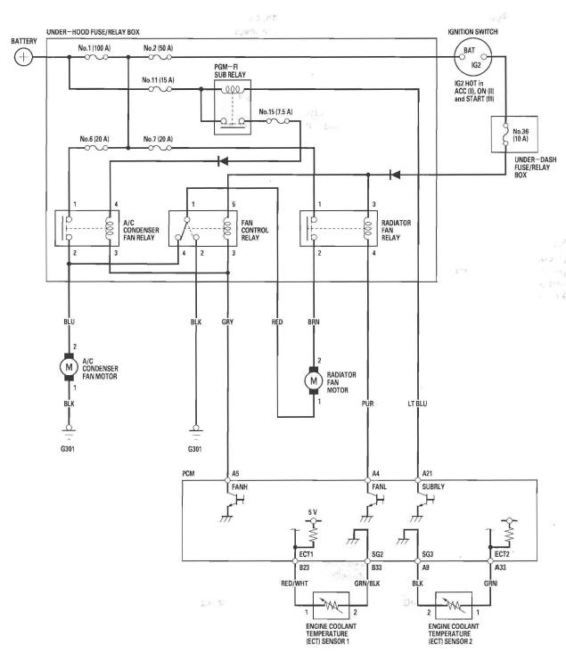
Circuit Diagram
Radiator Fan High Speed Circuit Troubleshooting
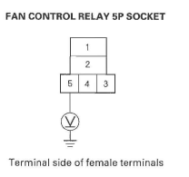
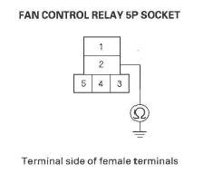
1. Remove the fan control relay from the under-hood fuse/relay box, and test it.
Is the relay OK?
YES-Go to step 2.
NO-Replace the fan control relay.
2. Measure the voltage between the fan control relay 5P socket terminal No. 5 and body ground.
Is there battery voltage? YES-Go to step 3.
NO-Replace the under-hood fuse/relay box.
3. Check for continuity between the fan control relay 5P socket terminal No.2 and body ground.
Is there continuity? YES-Replace the under-hood fuse/relay box.
NO-Repair open in the wire between the fan control relay 5P socket terminal No.2 and body ground. If the wire is OK, check for poor ground at G301.
READ NEXT:
 Fuel and Emissions Systems
Special Tools
Fuel Sender Wrench
Fuel Pressure Gauge Attachment Set
Vacuum/Pressure Gauge, 0-4 in.Hg
Pressure Gauge Adapter
Oil Pressure Hose
A/T Pressure Hose
A/T Low Pressure
General Troubleshooting Information
Intermittent Failures
The term "intermittent failure" means a system may
have had a failure, but it checks OK now. If the
malfunction indicator lamp (MIL) on the dash does not
come on, check for poor
SEE MORE:
Keys and Locks
The master key fits all the locks on
your vehicle. The valet key works
only in the ignition and the driver’s
door lock. You can keep the glove
box locked when you leave your
vehicle and the valet key at a parking
facility.
You should have received a key
number tag with your keys
Fuel Pressure Relieving
Before disconnecting fuel lines or hoses, relieve
pressure from the system by disabling the fuel pump
and then disconnecting the fuel tube/quick connect
fitting in the engine compartment.
With the HDS
1. Make sure you have the anti-theft code for the
audio system.
2. Remove the fuel fill cap, to re
