Honda CR-V: DTC U0028: F-CAN Malfunction (BUS-OFF (PCM) )
NOTE: Before you troubleshoot, record all freeze data and any on-board snapshot, and review the general troubleshooting information.
1. Turn the ignition switch ON (II).
2. Clear the DTC with the HDS.
3. Check for Temporary DTCs or DTCs with the HDS.
Is DTC U0028 indicated? YES-Update the PCM if it does not have the latest software, or substitute a known-good PCM , then recheck. If the symptom/indication goes away with a known-good PCM, replace the original PCM.
NO-Intermittent failure, the system is OK at this time.
DTC U0122: F-CAN Malfunction (PCM-VSA Modulator-Control Unit)
NOTE: Before you troubleshoot, record all freeze data and any on-board snapshot, and review the general troubleshooting information.
1. Turn the ignition switch ON (II).
2. Check for Temporary DTCs or DrCs with the HDS.
Are DTC U0028 and U0122 indicated at the same time? YES-Go to troubleshooting for DTC U0028.
NO-Go to step 3.
3. Clear the DTC with the HDS.
4. Check for Temporary DTCs or DTCs with the HDS.
Is DTC U0122 indicated? YES-Go to step 5.
NO-Intermittent failure, the system is OK at this time. Check for poor connections or loose terminals at the gauge control module, the VSA modulator-control unit, and the PCM.
5. Check for communication to the VSA system with the HDS.
Does the HDS communicate with the VSA modulator-control unit? YES-Go to step 6.
NO-Go to the DLC circuit troubleshooting.
6. Turn the ignition switch OFF.
7. Jump the SCS line with the HDS.
8. Disconnect the VSA modulator-control unit 46P connector.
9. Disconnect PCM connector A (44P).
10. Check for continuity between PCM connector terminal A36 and VSA modulator-control unit 46P connector terminal No. 39.
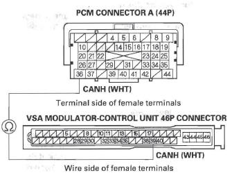
Is there continuity? YES-Go to step 11.
NO-Repair open in the wire between the PCM (A36) and the VSA modulator-control unit, then go to step 12.
11. Check for continuity between PCM connector terminal A37 and VSA modulator-control unit 46P connector terminal No. 38.
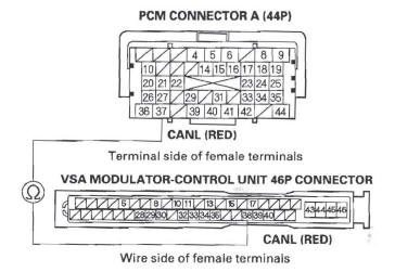
Is there continuity? YES-Substitute a known-good VSA modulator-control unit, then go to step 12 and recheck. If DTC U0122 is not indicated, replace the original VSA modulator-control unit, then go to step 12.
NO-Repair open in the wire between the PCM (A37) and the VSA modulator-control unit, then go to step 12.
12. Reconnect all connectors.
13. Turn the ignition switch ON (II).
14. Reset the PCM with the HDS.
15. Do the PCM idle learn procedure.
16. Check for Temporary DTCs or DTCs with the HDS.
Is DTC U0122 indicated? YES-Check for poor connections or loose terminals at the gauge control module, the VSA modulator unit, and the PCM, then go to step 1.
NO-Troubleshooting is complete. If any other Temporary DTCs or DTCs are indicated, go to the indicated DTC's troubleshooting.
DTC U0155: F-CAN Malfunction (PCM-Gauge Control Module)
NOTE: Before you troubleshoot, record all freeze data and any on-board snapshot, and review the general troubleshooting information.
1. Turn the ignition switch ON (II).
2. Clear the DTC with the HDS.
3. Check for Temporary DTCs or DTCs with the HDS.
Is DTC U0155 indicated? YES-Go to step 4.
NO-Intermittent failure, the system is OK at this time. Check for poor connections or loose terminals at the gauge control module and the PCM.
4. Check for body electrical DTCs in the DTCs MENU with the HDS.
Is DTC B1168, B1169, and/or B1178 indicated? YES-Go to step 5.
NO-Do the gauge control module input test.
5. Turn the ignition switch OFF.
6. Jump the SCS line with the HDS.
7. Remove the gauge control module.
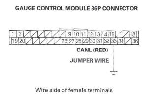
8. Disconnect the gauge control module 36P connector.
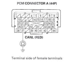
9. Disconnect PCM connector A (44P).
10. Connect gauge control module 36P connector terminal No. 34 to body ground with a jumper wire.
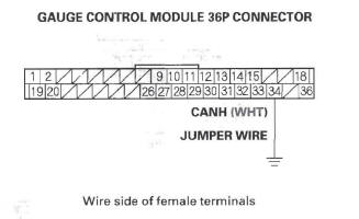
11. Check for continuity between PCM connector terminal A36 and body ground.
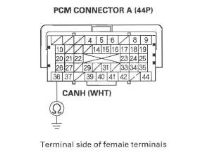
Is there continuity? YES-Go to step 12.
NO-Repair open in the wire between the PCM (A36) and the gauge control module, then go to step 14.
12. Connect gauge control module 36P connector terminal No. 33 to body ground with a jumper wire.
13. Check for continuity between PCM connector terminal A37 and body ground.
Is there continuity? YES-Substitute a known-good gauge control module, then go to step 14 and recheck. If no DTCs are indicated, replace the original gauge control module, then go to step 14.
NO-Repair open in the wire between the PCM (A37) and the gauge control module, then go to step 14.
14. Reconnect all connectors.
15. Turn the ignition switch ON (II).
16. Reset the PCM with the HDS.
17. Do the PCM idle learn procedure.
18. Check for Temporary DTCs or DTCs with the HDS.
Is DTC U0155 indicated? YES-Check for poor connections or loose terminals at the gauge control module and the PCM, then go to step 1.
NO-Troubleshooting is complete. If any other Temporary DTCs or DTCs are indicated, go to the indicated DTC's troubleshooting.
DTC U0300: PGM-FI System and A/T System Program Version Mismatch
NOTE:
- Before you troubleshoot, record all freeze data and any on-board snapshot, and review the general troubleshooting information.
- Do not turn the ignition switch OFF while updating the PCM. If you turn the ignition switch OFF before completion, the PCM will be damaged.
1. Do the PCM update procedure (PGM-FI system).
2. Do the PCM update procedure (A/T system).
3. Check for Temporary DTCs or DTCs with the HDS.
Is DTC U0300 indicated? YES-Replace the original PCM.
NO-Troubleshooting is complete. If any other Temporary DTCs or DTCs are indicated, go to the indicated DTC's troubleshooting.
READ NEXT:
 F-CAN Circuit Troubleshooting
NOTE: Information marked with an asterisk (*) applies
to the CANL line.
1. Turn the ignition switch OFF.
2. Jump the SCS line with the HDS.
3. Disconnect PCM connector A (44P), then disconnect
the
DLC Circuit Troubleshooting
NOTE: Make sure the HDS and the DLC cable of the
HDS is not defective.
1. Turn the ignition switch OFF.
2. Connect the HDS to the DLC.
NOTE: Make sure the HDS is properly connected to
the DLC.
3. T
Injector Replacement
1. Relieve fuel pressure.
2. Remove the engine cover.
3. Disconnect the connectors (A) from the injectors.
4. Remove the ground cable bolt (G101) (B).
5. Disconnect the quick-connect fitting (C).
SEE MORE:
Lap/Shoulder Belt
The lap/shoulder belt goes over
your shoulder, across your chest,
and across your hips.
To fasten the belt, insert the latch
plate into the buckle, then tug on the
belt to make sure the buckle is
latched (see page for how to
properly position the belt).
To unlock the belt, press the re
CD Changer Error Messages (EX-L model with navigation system)
If you see an error message in the
display while playing a disc, find the
cause in the chart to the right. If you
cannot clear the error message, take
your vehicle to your dealer.
The chart on the right explains the
error messages you may see in the
display while playing a disc.
If
