Honda CR-V: DTC P2227: BARD Sensor Range/Performance Problem
NOTE:
- Before you troubleshoot, record all freeze data and any on-board snapshot, and review the general troubleshooting information.
- If DTC P0101, P0108, P1128, and/or P1129 are stored at the same time as DTC P2221, troubleshoot those DTCs first, then recheck for DTC P2221.
1. Turn the ignition switch ON (II), and wait 2 seconds.
2. Check the BARO SENSOR in the DATA LIST with the HDS.
Is about 101 kPa (29.9 in.Hg, 760 mmHg), or about 2.9 V at sea level indicated? YES-Go to step 3.
NO-Go to step 1.
3. Clear the DTC with the HDS.
4. Start the engine. Hold the engine speed at 3,000 rpm without load (in Park or neutral) until the radiator fan comes on, then let it idle.
5. Test-drive under these conditions:
- Engine coolant temperature (ECT SENSOR 1) above 158 ºF (10 ºC)
- Transmission in D position
- REL TP SENSOR between 12 degrees and 20 degrees for 3 seconds
6. Monitor the OBD STATUS for DTC P2221 in the DTCs MENU with the HDS.
Does the screen indicate FAILED? YES-Go to step 1.
NO-If the screen indicates PASSED, intermittent failure, the system is OK at this time. If the screen indicates NOT COMPLETED, go to step 4 and recheck.
7. Update the PCM if it does not have the latest software, or substitute a known-good PCM.
8. Start the engine. Hold the engine speed at 3,000 rpm without load (in Park or neutral) until the radiator fan comes on, then let it idle.
9. Test-drive under these conditions:
- Engine coolant temperature (ECT SENSOR 1) above 158 ºF (10 ºC)
- Transmission in D position
- REL TP SENSOR between 12 degrees and 20 degrees for 3 seconds
10. Check for Temporary DTCs or DTCs with the HDS.
Is DTC P2227 indicated? YES-Check for poor connections or loose terminals at the PCM. lf the PCM was updated, substitute a known-good PCM, then go to step 8. If the PCM was substituted, go to step 1.
NO-Go to step 11.
11. Monitor the OBD STATUS for DTC P2221 in the DTCs MENU with the HDS.
Does the screen indicate PASSED? YES- If the PCM was updated, troubleshooting is complete. If the PCM was substituted, replace the original PCM. If any other Temporary DTCs or DTCs were indicated in step 10, go to the indicated DTC's troubleshooting.
NO-If the screen indicates FAILED, check for poor connections or loose terminals at the PCM. If the PCM was updated, substitute a known-good PCM, then go to step 8. If the PCM was substituted, go to step 1. If the screen indicates NOT COMPLETED, go to step 8 and recheck.
DTC P2228: BARO Sensor Circuit Low Voltage
NOTE: Before you troubleshoot, record all freeze data and any on-board snapshot, and review the general troubleshooting information.
1. Turn the ignition switch ON (II).
2. Check the BARO SENSOR in the DATA LIST with the HDS.
Is about 43 kPa (12.7 in.Hg, 323 mmHg), or 1.31 V or less indicated? YES-Go to step 3.
NO-Intermittent failure, the system is OK at this time.
3. Update the PCM if it does not have the latest software, or substitute a known-good PCM.
4. Check for Temporary DTCs or DTCs with the HDS.
Is DTC P2228 indicated? YES-Check for poor connections or loose terminals at the PCM. If the PCM was updated, substitute a known-good PCM, then recheck. If the PCM was substituted, go to step 1.
NO-If the PCM was updated, troubleshooting is complete. If the PCM was substituted, replace the original PCM. If any other Temporary DTCs or DTCs are indicated, go to the indicated DTC's troubleshooting.
DTC P2229: BARO Sensor Circuit High Voltage
NOTE: Before you troubleshoot; record all freeze data and any on-board snapshot, and review the general troubleshooting information.
1. Turn the ignition switch ON (II).
2. Check the BARO SENSOR in the DATA LIST with the HDS.
Is about 160 kPa (47.2 in.Hg, 1,200 mmHg), or 4.49 V or more indicated? YES-Go to step 3.
NO-Intermittent failure, the system is OK at this time.
3. Update the PCM if it does not have the latest software, or substitute a known-good PCM.
4. Check for Temporary DTCs or DTCs with the HDS.
Is DTC P2229 indicated? YES-Check for poor connections or loose terminals at the PCM. If the PCM was updated, substitute a known-good PCM, then recheck. If the PCM was substituted, go to step 1.
NO-If the PCM was updated, troubleshooting is complete. If the PCM was substituted, replace the original PCM. If any other Temporary DTCs or DTCs are indicated, go to the indicated DTC.'s troubleshooting.
DTC P2238: A/F Sensor (Sensor 1) AFS + Line Low Voltage
NOTE: Before you troubleshoot, record all freeze data and any on-board snapshot, and review the general troubleshooting information.
1. Turn the ignition switch ON (II).
2. Clear the DTC with the HDS.
3. Check for Temporary DTCs or DTCs with the HDS.
Is DTC P2238 indicated? YES-Go to step 4.
NO-Intermittent failure, the system is OK at this time. Check for poor connections or loose terminals at the A/F sensor (Sensor 1) and the PCM.
4. Turn the ignition switch OFF.
5. Jump the SCS line with the HDS.
6. Disconnect the A/F sensor (Sensor 1) 4P connector.
7. Disconnect PCM connector C (44P).
8. Check for continuity between PCM connector terminal C29 and body ground.
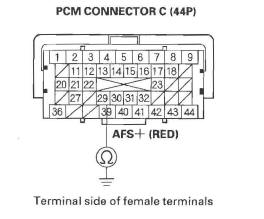
Is there continuity? YES-Repair short in the wire between the PCM (C29) and the A/F sensor (Sensor 1), then go to step 10.
NO-Go to step 9.
9. Replace the A/F sensor (Sensor 1).
10. Reconnect all connectors.
11. Turn the ignition switch ON (II).
12. Reset the PCM with the HDS.
13. Do the PCM idle learn procedure.
14. Check for Temporary DTCs or DTCs with the HDS.
Is DTC P2238 indicated? YES-Check for poor connections or loose terminals at the A/F sensor (Sensor 1) and the PCM, then go to step 1. If the connector and terminal fits are OK, go to step 16.
NO-Go to step 15.
15. Monitor the OBD STATUS for DTC P2238 in the DTCs MENU with the HDS.
Does the screen indicate PASSED? YES-Troubleshooting is complete. If any other Temporary DTCs or DTCs were indicated in step 14, go to the indicated DTC's troubleshooting.
NO-If the screen indicates FAILED, check for poor connections or loose terminals at the A/F sensor (Sensor 1) and the PCM, then go to step 1. If the screen indicates NOT COMPLETED, go to step 12.
16. Update the PCM if it does not have the latest software, or substitute a known-good PCM.
17. Start the engine.
18. Check for Temporary DTCs or DTCs with the HDS.
Is DTC P2238 indicated? YES-If the PCM was updated, substitute a known-good PCM, then go to step 17. If the PCM was substituted, go to step 1.
NO-Go to step 19.
19. Monitor the OBD STATUS for DTC P2238 in the DTCs MENU with the HDS.
Does the screen indicate PASSED? YES-If the PCM was updated, troubleshooting is complete. If the PCM was substituted, replace the original PCM. If any other Temporary DTCs or DTCs were indicated in step 18, go to the indicated DTC's troubleshooting.
NO-If the screen indicates FAILED, go to step 1. If the PCM was updated, substitute a known-good PCM , then go to step 17. If the PCM was substituted, go to step 1. If the screen indicates NOT COMPLETED, keep idling until a result comes on.
DTC P2252: A/F Sensor (Sensor 1) AFS - Line Low Voltage
NOTE: Before you troubleshoot, record all freeze data and any on-board snapshot, and review the general troubleshooting information.
1. Turn the ignition switch ON (II).
2. Clear the DTC with the HDS.
3. Start the engine.
4. Check for Temporary DTCs or DTCs with the HDS.
Is DTC P2252 indicated? YES-Go to step 5.
NO-Intermittent failure, the system is OK at this time. Check for poor connections or loose terminals at the A/F sensor (Sensor 1) and the PCM.
5. Turn the ignition switch OFF.
6. Jump the SCS line with the HDS.
7. Disconnect the A/F sensor (Sensor 1) 4P connector.
8. Disconnect PCM connector C (44P).
9. Check for continuity between PCM connector terminal C30 and body ground.
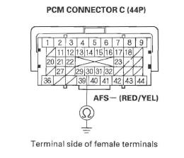
Is there continuity? YES-Repair short in the wire between the PCM (C30) and the A/F sensor (Sensor 1), then go to step 11.
NO-Go to step 10.
10. Replace the A/F sensor (Sensor 1).
11. Reconnect all connectors.
12. Turn the ignition switch ON (II).
13. Reset the PCM with the HDS.
14. Do the PCM idle learn procedure.
15. Check for Temporary DTCs or DTCs with the HDS.
Is DTC P2252 indicated? YES-Check for poor connections or loose terminals at the A/F sensor (Sensor 1) and the PCM, then go to step 1. If the connector and terminal fits are OK, go to step 17.
NO-Go to step 16.
16. Monitor the OBD STATUS for DTC P2252 in the DTCs MENU with the HDS.
Does the screen indicate PASSED? YES-Troubleshooting is complete. If any other Temporary DTCs or DTCs were indicated in step 15, go to the indicated DTC's troubleshooting.
NO-If the screen indicates FAILED, check for poor connections or loose terminals at the A/F sensor (Sensor 1) and the PCM, then go to step 1. If the screen indicates NOT COMPLETED, go to step 13.
17. Update the PCM if it does not have the latest software, or substitute a known-good PCM.
18. Start the engine.
19. Check for Temporary DTCs or DTCs with the HDS.
Is DTC P2252 indicated? YES-If the PCM was updated, substitute a known-good PCM, then go to step 18. lf the PCM was substituted, go to step 1.
NO-Go to step 20.
20. Monitor the OBD STATUS for DTC P2252 in the DTCs MENU with the HDS.
Does the screen indicate PASSED? YES-If the PCM was updated, troubleshooting is complete. If the PCM was substituted, replace the original PCM. If any other Temporary DTCs or DTCs were indicated in step 19, go to the indicated DTC's troubleshooting.
NO-If the screen indicates FAILED, go to step 1. If the PCM was updated, substitute a known-good PCM, then go to step 18. If the PCM was substituted, go to step 1. If the screen indicates NOT COMPLETED, keep idling until a result comes on.
READ NEXT:
 DTC P2270/P2271: Secondary HO2S (Sensor 2)
Circuit Signal Stuck Lean/Rich
DTC P2270/P2271: Secondary HO2S (Sensor 2)
Circuit Signal Stuck Lean/Rich
DTC P2270: Secondary HO2S (Sensor 2)
Circuit Signal Stuck Lean
DTC P2271: Secondary HO2S (Sensor 2)
Circuit Signal Stuck Rich
NOTE: Before you troubleshoot, record all freeze data and any on-board
sn
DTC U0028: F-CAN Malfunction (BUS-OFF
(PCM) )
NOTE: Before you troubleshoot, record all freeze data and any on-board
snapshot, and review the general troubleshooting information.
1. Turn the ignition switch ON (II).
2. Clear the DTC with the H
F-CAN Circuit Troubleshooting
NOTE: Information marked with an asterisk (*) applies
to the CANL line.
1. Turn the ignition switch OFF.
2. Jump the SCS line with the HDS.
3. Disconnect PCM connector A (44P), then disconnect
the
SEE MORE:
How Your Side Airbags Work
If you ever have a moderate to
severe side impact, sensors will
detect rapid acceleration and signal
the control unit to instantly inflate
either the driver’s or the passenger’s
side airbag and activate the seat belt
tensioner on the affected side.
Only one airbag will deploy du
Carrying Cargo on the Dual Deck Cargo Shelf
If equipped
On U.S. model is shown
Do not put any items on the dual
deck cargo shelf that could block
your view or be thrown around the
vehicle during a crash.
Do not use the dual deck cargo shelf
if the rear seats are folded down.
Do not exceed the dual deck cargo
shelf load limit o
