Honda CR-V: DTC P2101: Electronic Throttle Control System (ETCS) Malfunction
CAUTION
Do not insert your fingers into the installed throttle body when you turn the ignition switch ON (II) or while the ignition switch is ON (II). If you do, you will seriously injure your fingers if the throttle valve is activated.
NOTE: Before you troubleshoot, record all freeze data and any on-board snapshot, and review the general troubleshooting information.
1. Turn the ignition switch ON (II).
2. Clear the DTC with the HDS.
3. Do the ETCS TEST in the INSPECTION MENU with the HDS.
4. Check for Temporary DTCs or DTCs with the HDS.
Is DTC P2101 indicated? YES-Go to step 7.
NO-Go to step 5.
5. Test-drive the vehicle for several minutes in the range of these recorded freeze data parameters:
- ENGINE SPEED
- VSS
- APP SENSOR
6. Check for Temporary DTCs or DTCs with the HDS.
Is DTC P2101 indicated? YES-Go to step 7.
NO-Intermittent failure, the system is OK at this time. Check for poor connections or loose terminals at the throttle body and the PCM, then clean the throttle body.
7. Turn the ignition switch OFF.
8. Disconnect the air intake duct from the throttle body.
9. Turn the ignition switch ON (II).
10. Clear the DTC with the HDS.
11. Do the ETCS TEST in the INSPECTION MENU with the HDS.
12. Visually check the throttle valve operation.
Does the throttle valve operate smoothly? YES-Clean the throttle body, then go to step 22 and recheck. If DTC P2101 is indicated, go to step 19.
NO-Go to step 13.
13. Turn the ignition switch OFF.
14. Disconnect the throttle body 6P connector.
15. Jump the SCS line with the HDS.
16. Disconnect PCM connector C (44P).
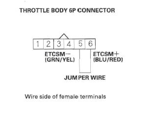
17. Connect throttle body 6P connector terminals No.5 and No.6 with a jumper wire.

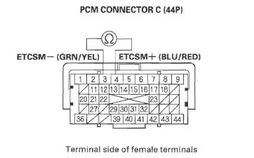
18. Check for continuity between PCM connector terminals C3 and C4.

Is there continuity? YES-Go to step 27.
NO-Repair open in the wires between the throttle body and the PCM (C3, C4), then go to step 21.
19. Turn the ignition switch OFF.
20. Replace the throttle body.
21. Reconnect all connectors.
22. Turn the ignition switch ON (II).
23. Reset the PCM with the HDS.
24. Do the PCM idle learn procedure.
25. Test-drive the vehicle for several minutes in the range of these recorded freeze data parameters:
- ENGINE SPEED
- VSS
- APP SENSOR
26. Check for Temporary DTCs or DTCs with the HDS.
Is DTC P2101 indicated? YES-Check for poor connections or loose terminals at the throttle body and the PCM, then clean the throttle body, and go to step 1.
NO-Troubleshooting is complete. If any other Temporary DTCs or DTCs are indicated, go to the indicated DTC's troubleshooting.
27. Reconnect all connectors.
28. Update the PCM if it does not have the latest software, or substitute a known-good PCM.
29. Test-drive the vehicle for several minutes in the range of these recorded freeze data parameters:
- ENGINE SPEED
- VSS
- APP SENSOR
30. Check for Temporary DTCs or DTCs with the HDS.
Is DTC P2101 indicated? YES-Check for poor connections or loose terminals at the throttle body and the PCM. If the PCM was updated, substitute a known-good PCM, then go to step 29. If the PCM was substituted, go to step 1.
NO-If the PCM was updated, troubleshooting is complete. If the PCM was substituted, replace the original PCM. If any other Temporary DTCs or DTCs are indicated, go to the indicated DTC's troubleshooting.
DTC P2118: Throttle Actuator Current Rangel Performance Problem
NOTE: Before you troubleshoot, record all freeze data and any on-board snapshot, and review the general troubleshooting information.
1. Jump the SCS line with the HDS.
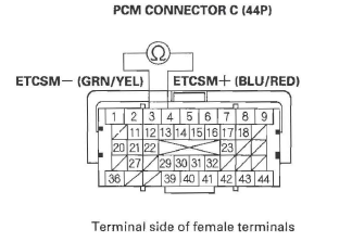
2. Disconnect PCM connector C (44P).
3. Measure resistance between PCM connector terminals C3 and C4.

Is there about 1.0 Ω or less? YES-Go to step 4.
NO-Go to step 15.
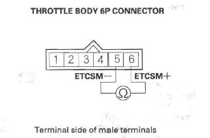
4. Disconnect the throttle body 6P connector.
5. At the throttle body side, measure resistance between throttle body 6P connector terminals No.5 and No.6 with the throttle fully closed.

Is there about 1.0 Ω or less? YES-Go to step 6.
NO-Repair short in the wires between PCM G3 (ETCSM - line) and C4 (ETCSM + line), then go to step 7.
6. Replace the throttle body.
7. Reconnect all connectors.
8. Turn the ignition switch ON (II).
9. Reset the PCM with the HDS.
10. Do the PCM idle learn procedure.
11. Turn the ignition switch OFF.
12. Turn the ignition switch ON (II).
13. Slowly press the accelerator pedal to the floor.
14. Check for Temporary DTCs or DTCs with the HDS.
Is DTC P2118 indicated? YES-Check for poor connections or loose terminals at the throttle body and the PCM, then go to step 1.
NO-Troubleshooting is complete. If any other Temporary DTCs or DTCs are indicated, go to the indicated DTC's troubleshooting.
15. Reconnect all connectors.
16. Update the PCM if it does not have the latest software, or substitute a known-good PCM.
17. Turn the ignition switch OFF.
18. Turn the ignition switch ON (II).
19. Slowly press the accelerator pedal to the floor.
20. Check for Temporary DTCs or DTCs with the HDS.
Is DTC P2118 indicated? YES-Check for poor connections or loose terminals at the throttle body and the PCM. If the PCM was updated, substitute a known-good PCM, then go to step 17. If the PCM was substituted, go to step 1.
NO-If the PCM was updated, troubleshooting is complete. If the PCM was substituted, replace the original PCM . If any other Temporary DTCs or DTCs are indicated, go to the indicated DTC's troubleshooting.

