Honda CR-V: DTC P1549: Charging System High Voltage
NOTE:
- Before you troubleshoot, record all freeze data and any on-board snapshot, and review the general troubleshooting information.
- If a high voltage battery (24 V, etc.) is connected to the vehicle, this DTC can be stored.
1. Turn the ignition switch ON (II).
2. Clear the DTC with the HDS.
3. Start the engine.
4. Check under these conditions:
- A/C off
- Headlights off
- Rear window defogger off
5. Hold the engine speed at 2,000 rpm (in Park or neutral) for 1 minute.
6. Check for Temporary DTCs or DTCs with the HDS.
Is DTC P1549 indicated? YES-Replace the alternator, then go to step 7.
NO-Intermittent failure, the system is OK at this time. Check for poor connections or loose terminals at the alternator and the under-hood fuse/relay box.
7. Turn the ignition switch ON (II).
8. Reset the PCM with the HDS.
9. Do the PCM idle learn procedure.
10. Start the engine.
11. Check under these conditions:
- A/C off
- Headlights off
- Rear window defogger off
12. Hold the engine speed at 2,000 rpm (in Park or neutral) for 1 minute.
13. Check for Temporary DTCs or DTCs with the HDS.
Is DTC P1549 indicated? YES-Check for poor connections or loose terminals at the alternator and the under-hood fuse/relay box, then go to step 1.
NO-Troubleshooting is complete. If any other Temporary DTCs or DTCs are indicated, go to the indicated DTC's troubleshooting.
DTC P16BB: Alternator B Terminal Circuit Low Voltage
NOTE: Before you troubleshoot, record all freeze data and any on-board snapshot, and review the general troubleshooting information.
1. Turn the ignition switch ON (II).
2. Clear the DTC with HDS.
3. Start the engine.
4. Check under these conditions:
- A/C on
- Temperature control at maximum cool
- Blower fan at maximum speed
- Rear window defogger on
- Headlights on high beam
5. Hold the engine speed at 2,000 rpm (in Park or neutral) for 1 minute.
6. Check for Temporary DTCs or DTCs with the HDS.
Is DTC P16BB indicated? YES-Go to step 7.
NO-Intermittent failure, the system is OK at this time. Check for poor connections or loose terminals at the alternator and the under-hood fuse/relay box, and check the battery performance.
7. Check for poor connections or loose terminals at the alternator and the under-hood fuse/relay box (+B line).
Are the connections and terminals OK? YES-Go to step 8.
NO-Repair the connectors or terminals, then go to step 9.
8. Check for an open in the wire between the alternator and under-hood fuse/relay box at the starter subharness.
Is the harness OK? YES-Replace the alternator, then go to step 9.
NO-Repair open in the wire between the alternator and the under-hood fuse/relay box, then go to step 9.
9. Turn the ignition switch ON (II).
10. Reset the PCM with the HDS.
11. Do the PCM idle learn procedure.
12. Start the engine.
13. Check under these conditions:
- A/C on
- Temperature control at maximum cool
- Blower fan at maximum speed
- Rear window defogger on
- Headlights on high beam
14. Hold the engine speed at 2,000 rpm (in Park or neutral) for 1 minute.
15. Check for Temporary DTCs or DTCs with the HDS.
Is DTC P16BB indicated? YES-Check for poor connections or loose terminals at the alternator and the under-hood fuse/relay box, then go to step 1.
NO-Troubleshooting is complete. If any other Temporary DTCs or DTCs are indicated, go to the indicated DTC's troubleshooting.
DTC P16BC: Alternator FR Terminal Circuit/IGP Circuit Low Voltage
NOTE: Before you troubleshoot, record all freeze data and any on-board snapshot, and review the general troubleshooting information.
1. Check for poor connections or loose terminals at the alternator 4P connector.
Are the connections and terminals OK? YES-Go to step 2.
NO-Repair the connector or terminals, then go to step 18.
2. Check the alternator mounting surface for corrosion.
Is the mounting surface corroded? YES-Remove the alternator. Clean all mounting surfaces, reinstall the alternator, then go to step 18.
NO-Go to step 3.
3. Turn the ignition switch ON (II).
4. Clear the DTC with the HDS.
5. Start the engine.
6. Check under these conditions:
- A/C on
- Temperature control at maximum cool
- Blower fan at maximum speed
- Rear window defogger on
- Headlights on high beam
7. Hold the engine speed 2,000 rpm (in Park or neutral) for 1 minute.
8. Check for Temporary DTCs or DTCs with the HDS.
Is DTC P16BC indicated? YES-Go to step 9.
NO-Intermittent failure, the system is OK at this time. Check for poor connections or loose terminals at the alternator.
9. Turn the ignition switch OFF.
10. Disconnect the alternator 4P connector.
11. Turn the ignition switch ON (II).
12. Measure voltage between alternator 4P connector terminal NO.1 and body ground.
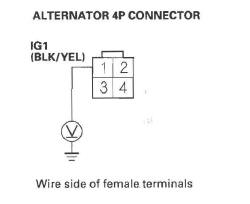
Is there battery voltage? YES-Go to step 13.
NO-Repair open in the wire between the alternator (lG1 line) and the No. 3 ALTERNATOR (10 A) fuse in the under-dash fuse/relay box, then go to step 18.
13. Measure voltage between alternator 4P connector terminal No.4 and body ground.
Is there about 5 V? YES-Replace the alternator, then go to step 18.
NO-Go to step 14.
14. Turn the ignition switch OFF.
15. Jump the SCS line with the HDS.
16. Disconnect PCM connector B (44P).
17. Check for continuity between alternator 4P connector terminal No. 4 and PCM connector terminal B43.
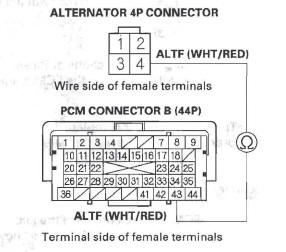
Is there continuity? YES-Go to step 27.
NO-Repair open in the wire between the PCM (B43) and the alternator, then go to step 18.
18. Turn the ignition switch OFF.
19. Reconnect all connectors.
20. Turn the ignition switch ON (II).
21. Reset the PCM with the HDS.
22. Do the PCM idle learn procedure.
23. Start the engine.
24. Check under these conditions:
- A/C on
- Temperature control at maximum cool
- Blower fan at maximum speed
- Rear window defogger on
- Headlights on high beam
25. Hold the engine speed 2,000 rpm (in Park or neutral) for 1 minute.
26. Check for Temporary DTCs or DTCs with the HDS.
Is DTC P16BC indicated? YES-Check for poor connections or loose terminals at the alternator and the PCM, then go to step 1.
NO-Troubleshooting is complete. If any other Temporary DTCs or DTCs are indicated, go to the indicated DTC's troubleshooting.
27. Reconnect all connectors.
28. Update the PCM if it does not have the latest software, or substitute a known-good PCM.
29. Start the engine.
30. Check under these conditions:
- A/C on
- Temperature control at maximum cool
- Blower fan at maximum speed
- Rear window defogger on
- Headlights on high beam
31. Hold the engine speed 2,000 rpm (in Park or neutral) for 1 minute.
32. Check for Temporary DTCs or DTCs with the HDS.
Is DTC P16BC indicated? YES-Check for poor connections or loose terminals at the alternator and the PCM. If the PCM was updated, substitute a known-good PCM, then go to step 29. If the PCM was substituted, go to step 1.
NO-If the PCM was updated, troubleshooting is complete. If the PCM was substituted, replace the original PCM. If any other Temporary DTCs or DTCs are indicated, go to the indicated DTC's troubleshooting.
DTC P2183: ECT Sensor 2 Range/ Performance Problem
NOTE:
- Before you troubleshoot, record all freeze data and any on-board snapshot, and review the general troubleshooting information.
- If DTC P0111 is stored at the same time as DTC P2183, troubleshoot DTC POll1 first, then recheck for DTC P2183.
1. Check for poor, connections or loose terminals at ECT sensor 1 and ECT sensor 2.
Are the connections and terminals OK? YES-Go to step 2.
NO-Repair the connectors or terminals, then go to step 27.
2. Turn the ignition switch ON (II).
3. Check for Temporary DTCs or DTCs with the HDS.
Are DTC P1116 and P2183 indicated at the same time? YES-Go to step 15.
NO-Go to step 4.
4. Start the engine, and let it idle 10 minutes.
5. Check ECT SENSOR 2 in the DATA LIST with the HDS.
Is about 131 ºF (55 ºC) or less, or 1.50 V or more indicated? YES-Replace ECT sensor 2, then go to step 27.
NO-Go to step 6.
6. Turn the ignition switch OFF.
7. Drain the coolant.
8. Remove ECT sensor 2.
9. Allow ECT sensor 2 to cool to ambient temperature.
10. Note the ambient temperature.
11. Connect ECT sensor 2 to its 2P connector, but do not install it on the engine.
12. Turn the ignition switch ON (II).
13. Note the value of ECT SENSOR 2 quickly in the DATA LIST with the HDS.
14. Compare the value of ECT SENSOR 2 and the ambient temperature.
Does ECT SENSOR 2 differ 5.4 F (3ºC) or more? YES-Replace ECT sensor 2, then go to step 27.
NO-Intermittent failure, the system is OK at this time. Check for, poor connections or loose terminals at ECT sensor 1, ECT sensor 2, and the PCM.
15. Start the engine, and let it idle 10 minutes.
16. Check ECT SENSOR 1 in the DATA LIST with the HDS.
Is about 118 F (48ºC) or less, or 1.75 V or more indicated? YES-Replace ECT sensor 1, then go to step 27.
NO-Go to step 17.
17. Let the engine idle 10 minutes.
18. Check ECT SENSOR 2 in the DATA LIST with the HDS.
Is about 131ºF (55 ºC) or less, or 1.50 V or more indicated? YES-Replace ECT sensor 2, then go to step 27.
NO-Go to step 19.
19. Turn the ignition switch OFF.
20. Drain the coolant.
21. Remove ECT sensor 1 and ECT sensor 2.
22. Allow the sensors to cool to ambient temperature.
23. Note the ambient temperature.
24. Connect ECT sensor 1 to its 2P connector, and ECT sensor 2 to its 2P connector, but do not install them on the engine.
25. Note the value of ECT SENSOR 1 and ECT SENSOR 2 quickly in the DATA LIST with the HDS.
26. Compare the value of ECT SENSOR 1 and the ambient temperature, and the value of ECT SENSOR 2 and the ambient temperature individually.
Does one of the sensors differ more than 5.4 F (3 ºC) from the ambient temperature? YES-Replace the sensor that differed more than 5.4ºF (3 ºC) from the ambient temperature, then go to step 27.
NO-Intermittent failure, the system is OK at this time. Check for poor connections or loose terminals at ECT sensor 1, ECT sensor 2, and the PCM.
27. Turn the ignition switch ON (II).
28. Reset the PCM with the HDS.
29. Do the PCM idle learn procedure.
30. Check for Temporary DTCs or DTCs with the HDS.
Is DTC P2183 indicated? YES-Check for poor connections or loose terminals at ECT sensor 1, ECT sensor 2, and the PCM, then go to step 1.
NO-Troubleshooting is complete. If any other Temporary DTCs or DTCs are indicated, go to the indicated DTC's troubleshooting.
DTC P2184: ECT Sensor 2 Circuit Low Voltage
NOTE: Before you troubleshoot, record all freeze data and any on-board snapshot, and review the general troubleshooting information.
1. Turn the ignition switch ON (II).
2. Check ECT SENSOR 2 in the DATA LIST with the HDS.
Is about 356 F (180 ºC) or more, or 0.08 V or less indicated? YES-Go to step 3.
NO-Intermittent failure, the system is OK at this time. Check for poor connections or loose terminals at ECT sensor 2 and the PCM.
3. Turn the ignition switch OFF.
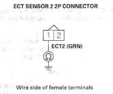
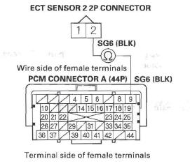
4. Disconnect the ECT sensor 2 2P connector.
5. Turn the ignition switch ON (II).
6. Check ECT SENSOR 2 in the DATA LIST with the HDS.
Is about 356 F (180 ºC) or more, or 0.08 V or less indicated? YES-Go to step 7.
NO-Go to step 11.
7. Turn the ignition switch OFF.
8. Jump the SCS line with the HDS.
9. Disconnect PCM connector A (44P).
10. Check for continuity between ECT sensor 2 2P connector terminal No.1 and body ground.
Is there continuity? YES-Repair short in the wire between ECT sensor 2 and the PCM (A33), then go to step 13.
NO-Go to step 18.
11. Turn the ignition switch OFF.
12. Replace ECT sensor 2.
13. Reconnect all connectors.
14. Turn the ignition switch ON (II).
15. Reset the PCM with the HDS.
16. Do the PCM idle learn procedure.
17. Check for Temporary DTCs or DTCs with the HDS.
Is DTC P2184 indicated? YES-Check for poor connections or loose terminals at ECT sensor 2 and the PCM, then go to step 1.
NO-Troubleshooting is complete. If any other Temporary DTCs or DTCs are indicated, go to the indicated DTC's troubleshooting.
18. Reconnect all connectors.
19. Update the PCM if it does not have the latest software, or substitute a known-good PCM.
20. Check for Temporary DTCs or DTCs with the HDS.
Is DTC P2184 indicated? YES-Check for poor connections or loose terminals at ECT sensor 2 and the PCM. If the PCM was updated, substitute a known-good PCM, then recheck. If the PCM was substituted, go to step 1.
NO-If the PCM was updated, troubleshooting is complete. If the PCM was substituted, replace the original PCM. If any other Temporary DTCs or DTCs are indicated, go to the indicated DTC's troubleshooting.
DTC P2185: ECT Sensor 2 Circuit High Voltage
NOTE: Before you troubleshoot, record all freeze data and any on-board snapshot, and review the general troubleshooting information.
1. Turn the ignition switch ON (II).
2. Check ECT SENSOR 2 in the DATA LIST with the HDS.
Is about - 40 F (-40 ºC) or less, or 4.90 V or more indicated? YES-Go to step 3.
NO-Intermittent failure, the system is OK at this time. Check for poor connections or loose terminals at ECT sensor 2 and the PCM.
3. Turn the ignition switch OFF.
4. Disconnect the ECT sensor 2 2P connector.
5. Connect ECT sensor 2 2P connector terminals No.1 and No.2 with a jumper wire.

6. Turn the ignition switch ON (II).
7. Check ECT SENSOR 2 in the DATA LIST with the HDS.
Is about - 40 F (-40 C) or less, or 4.90 V or more indicated? YES-Go to step 8.
NO-Go to step 20.
8. Turn the ignition switch OFF.
9. Remove the jumper wire from the ECT sensor 2 2P connector.
10. Turn the ignition switch ON (II).
11. Measure voltage between ECT sensor 2 2P connector terminal No. 1 and body ground.
Is there about 5 V? YES-Go to step 12.
NO-Go to step 16.
12. Turn the ignition switch OFF.
13. Jump the SCS line with the HDS.
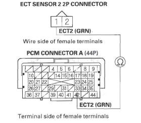
14. Disconnect PCM connector A (44P).
15. Check for continuity between ECT sensor 2 2P connector terminal No. 2 and PCM connector terminal A9.
Is there continuity? YES-Go to step 27.
NO-Repair open in the wire between the PCM (A9) and ECT sensor 2, then go to step 22.
16. Turn the ignition switch OFF.
17. Jump the SCS line with the HDS.
18. Disconnect PCM connector A (44P).
19. Check for continuity between ECT sensor 2 2P connector terminal No.1 and PCM connector terminal A33.
Is there continuity? YES-Go to step 27.
NO-Repair open in the wire between the PCM (A33) and ECT sensor 2, then go to step 22.
20. Turn the ignition switch OFF.
21. Replace ECT sensor 2.
22. Reconnect all connectors.
23. Turn the ignition switch ON (II).
24. Reset the PCM with the HDS.
25. Do the PCM idle learn procedure.
26. Check for Temporary DTCs or DTCs with the HDS.
Is DTC P2185 indicated? YES-Check for poor connections or loose terminals at ECT sensor 2 and the PCM, then go to step 1.
NO-Troubleshooting is complete. If any other Temporary DTCs or DTCs are indicated, go to the indicated DTC's troubleshooting.
27. Reconnect all connectors.
28. Update the PCM if it does not have the latest software, or substitute a known-good PCM.
29. Check for Temporary DTCs or DTCs with the HDS.
Is DTC P2185 indicated? YES-Check for poor connections or loose terminals at ECT sensor 2 and the PCM. If the PCM was updated, substitute a known-good PCM, then recheck. If the PCM was substituted, go to step 1.
NO-If the PCM was updated, troubleshooting is complete. If the PCM was substituted, replace the original PCM. If any other Temporary DTCs or DTCs are indicated, go to the indicated DTC's troubleshooting.
DTC P2195: A/F Sensor (Sensor 1) Signal Stuck Lean
NOTE:
- Before you troubleshoot, record all freeze data and any on-board snapshot, and review the general troubleshooting information.
- If the vehicle was out of fuel and the engine stalled before this DTC was stored, refuel and clear the DTC with the HDS.
- If DTC P2101, P2118, P2135, P2138, P2176, or a combination of P2122 and P2127, P2122, and P2138, or P2127 and P2138 is stored at the same time, troubleshoot them first, then recheck for DTC P2195.
1. Check the installation of the A/F sensor (Sensor 1).
Is the A/F sensor loose or disconnected from the exhaust pipe? YES-Go to step 6.
NO-Go to step 2.
2. Turn the ignition switch ON (II).
3. Clear the DTC with the HDS.
4. Start the engine. Hold the engine speed at 3,000 rpm without load (in Park or neutral) until the radiator fan comes on, then let it idle.
5. Check for Temporary DTCs or DTCs with the HDS.
Are any Temporary DTCs or DTCs indicated? YES-If DTC P2195 is indicated, check for poor connections or loose terminals at the A/F sensor (Sensor 1) and the PCM, then go to step 13. If any other Temporary DTCs or DTCs are indicated, go to the indicated DTC's troubleshooting.
NO-Intermittent failure, the system is OK at this time. Check for poor connections or loose terminals at the A/F sensor (Sensor 1) and the PCM.
6. Turn the ignition switch OFF.
7. Reinstall the A/F sensor (Sensor 1).
8. Turn the ignition switch ON (II).
9. Reset the PCM with the HDS.
10. Do the PCM idle learn procedure.
11. Check for Temporary DTCs or DTCs with the HDS.
Is DTC P2195 indicated? YES-Check for poor connections or loose terminals at the A/F sensor (Sensor 1) and the PCM, then go to step 1.
NO-Go to step 12.
12. Monitor the OBD STATUS for DTC P2195 in the DTCs MENU with the HDS.
Does the screen indicate PASSED? YES-Troubleshooting is complete. If any other Temporary DTCs or DTCs were indicated in step 11, go to the indicated DTC's troubleshooting.
NO-If the screen indicates FAILED, check for poor connections or loose terminals at the A/F sensor (Sensor 1) and the PCM, then go to step 1. If the screen indicated NOT COMPLETED, go to step 10.
13. Update the PCM if it does not have the latest software, or substitute a known-good PCM.
14. Start the engine. Hold the engine speed at 3,000 rpm without load (in Park or neutral) until the radiator fan comes on, then let it idle.
15. Check for Temporary DTCs or DTCs with the HDS.
Is DTC P2195 indicated? YES-Check for poor connections or loose terminals at the A/F sensor (Sensor 1) and the PCM.
If the PCM was updated, substitute a known-good PCM, then go to step 14. If the PCM was substituted, go to step 1.
NO-Go to step 16.
16. Monitor the OBD STATUS for DTC P2195 in the DTCs MENU with the HDS.
Does the screen indicate PASSED? YES-If the PCM was updated, troubleshooting is complete. If the PCM was substituted, replace the original PCM.
NO-If the screen indicates FAILED, check for poor connections or loose terminals at the A/F sensor (Sensor 1) and the PCM. If the PCM was updated, substitute a known-good PCM, then go to step 14. If the PCM was substituted, go to step 1. If the screen indicates NOT COMPLETED, go to step 14.
READ NEXT:
 DTC P2227: BARD Sensor Range/Performance Problem
NOTE:
Before you troubleshoot, record all freeze data and any on-board
snapshot, and review the general troubleshooting information.
If DTC P0101, P0108, P1128, and/or P1129 are stored
at the sa
DTC P2270/P2271: Secondary HO2S (Sensor 2)
Circuit Signal Stuck Lean/Rich
DTC P2270: Secondary HO2S (Sensor 2)
Circuit Signal Stuck Lean
DTC P2271: Secondary HO2S (Sensor 2)
Circuit Signal Stuck Rich
NOTE: Before you troubleshoot, record all freeze data and any on-board
sn
DTC U0028: F-CAN Malfunction (BUS-OFF
(PCM) )
NOTE: Before you troubleshoot, record all freeze data and any on-board
snapshot, and review the general troubleshooting information.
1. Turn the ignition switch ON (II).
2. Clear the DTC with the H
SEE MORE:
Rear Seat Adjustments
To adjust the seats forward and
backward, pull up on the lever under
the seat cushion. After moving the
seat, make sure it is locked into
position.
The angle of each rear seat-back can
be adjusted separately. To change
the seat-back angle of the rear seatback,
pull up on the relea
Glove Box Removal/Installation
NOTE: Take care not to scratch the dashboard and
related parts.
1. Open the glove box (A), and detach the hook (B) of
the glove box damper. While holding the glove box,
release the glove box stop (C) on each side from
the dashboard by pushing them in.
2. Close the glove box (A), then remove the bo
