Honda CR-V: DTC P0128: Cooling System Malfunction
NOTE: Before you troubleshoot, record all freeze data and any on-board snapshot, and review the general troubleshooting information.
1. Turn the ignition switch ON (II).
2. Clear the DTC with the HDS.
3. Turn the blower switch OFF.
4. Check the FAN CTRL in the DATA LIST with the HDS.
Is it OFF? YES-Go to step 5.
NO-Wait until the FAN CTRL is off, then go to step 5.
5. Check the radiator fan operation.
Does the radiator fan keep running? YES-Check the radiator fan circuit, and the radiator fan relay.
If the circuits and the relay are OK, go to step 19.
NO-Go to step 6.
6. Let the engine cool until the coolant temperature is 104ºF (40 ºC) or less.
7. Note the value of ECT SENSOR 1 and ECT SENSOR 2 in the DATA LIST with the HDS.
8. Start the engine, and let it idle.
9. Let the engine idle until ECT SENSOR 1 goes up 49 ºF (27 ºC) or more from the recorded temperature.
10. Check ECT SENSOR 2 in the DATA LIST with the HDS.
11. Compare the value of recorded ECT SENSOR 2 and the present value of ECT SENSOR 2.
Did the temperature rise 17 ºF (9.5 ºC) or more? YES-Intermittent failure, the system is OK at this time. Check for poor connections or loose terminals at ECT sensor 1, ECT sensor 2, and the PCM.
NO-Test the thermostat , then go to step 12.
12. Turn the ignition switch ON (II).
13. Reset the PCM with the HDS.
14. Let the engine cool until the coolant temperature is between 21 ºF (-6 ºC) and 104 ºF (40 ºC).
15. Do the PCM idle learn procedure.
16. Test-drive at a steady speed between 15- 75 mph (24-120 km/h) for 10 minutes.
17. Check for Temporary DTCs or DTCs with the HDS.
Is DTG P0128 indicated? YES-Check the cooling system, then go to step 1.
NO-Go to step 18.
18. Monitor the OBD STATUS for DTC P0128 in the DTCs MENU with the HDS.
Does the screen indicate PASSED? YES-Troubleshooting is complete. If any other Temporary DTCs or DTCs were indicated in step 17, go to the indicated DTC's troubleshooting.
NO-If the screen indicates FAILED, check the cooling system, then go to step 1. If the screen indicates NOT COMPLETED, go to step 14.
19. Update the PCM if it does not have the latest software or substitute a known-good PCM.
20. Let the engine cool until the coolant temperature is between 21 ºF (-6 ºC) and 104 ºF (40 ºC).
21. Start the engine. Hold the engine speed at 3,000 rpm without load (in Park or neutral) until the radiator fan comes on, then let it idle.
22. Test-drive at a steady speed between 15-75 mph (24-120 km/h) for 10 minutes.
23. Check for Temporary DTCs or DTCs with the HDS.
Is DTC P0128 indicated? YES-Check for poor connections or loose terminals at ECT sensor 1, ECT sensor 2, and the PCM. If the PCM was updated, substitute a known-good PCM, then go to step 20. If the PCM was substituted, go to step 1.
NO-Go to step 24.
24. Monitor the OBD STATUS for DTC P0128 in the DTCs MENU with the HDS.
Does the screen indicate PASSED? YES-If the PCM was updated, troubleshooting is complete. If the PCM was substituted, replace the original PCM. If any other Temporary DTCs or DTCs were indicated in step 23, go to the indicated DTC's troubleshooting.
NO-If the screen indicates FAILED, check for poor connections or loose terminals at ECT sensor 1, ECT sensor 2, and the PCM. If the PCM was updated, substitute a known-good PCM, then go to step 20. If the PCM was substituted, go to step 1. If the screen indicates NOT COMPLETED, go to step 20.
DTC P0133: A/F Sensor (Sensor 1) Response Malfunction/Slow Response
NOTE: Before you troubleshoot, record all freeze data and any on-board snapshot, and review the general troubleshooting information.
1. Turn the ignition switch ON (II).
2. Clear the DTC with the HDS.
3. Start the engine. Hold the engine speed at 3,000 rpm without load (in Park or neutral) until the radiator fan comes on, then let it idle.
4. Test-drive under these conditions:
- Engine coolant temperature (ECT SENSOR 1) above 176 ºF (80 ºC)
- Transmission in D position
- Drive the vehicle at 25 mph (40 km/h) or less for 5 minutes, then drive at a steady speed between 26-81 mph (41-130 km/h).
5. Monitor the OBD STATUS for DTC P0133 in the DTCs MENU with the HDS.
Does the screen indicate FAILED? YES-Go to step 6.
NO-If the screen indicates PASSED, intermittent failure, the system is OK at this time. Check for poor connections or loose terminals at the A/F sensor (Sensor 1) and the PCM. If the screen indicates EXECUTING, keep driving until a result comes on. If the screen indicates OUT OF CONDITION, go to step 3 and recheck.
6. Turn the ignition switch OFF.
7. Replace the A/F sensor (Sensor 1).
8. Turn the ignition switch ON (II).
9. Reset the PCM with the HDS.
10. Do the PCM idle learn procedure.
11. Start the engine. Hold the engine speed at 3,000 rpm without load (in Park or neutral) until the radiator fan comes on, then let it idle.
12. Test-drive under these conditions:
- Engine coolant temperature (ECT SENSOR 1) above 176 ºF (80 ºC)
- Transmission in D position
- Drive the vehicle at 25 mph (40 km/h) or less for 5 minutes, then drive at a steady speed between 26-81 mph (41-130 km/h).
13. Check for Temporary DTCs or DTCs with the HDS.
Is DTC P0133 indicated? YES-Check for poor connections or loose terminals at the A/F sensor (Sensor 1) and the PCM, then go to step 1.
NO-Go to step 14.
14. Monitor the OBD STATUS for DTC P0133 in the DTCs MENU with the HDS.
Does the screen indicate PASSED? YES-Troubleshooting is complete. If any other Temporary DTCs or DTCs were indicated in step 13, go to the indicated DTC's troubleshooting.
NO-If the screen indicates FAILED, check for poor connections or loose terminals at the A/F sensor (Sensor 1) and the PCM, then go to step 1. If the screen indicates EXECUTING, keep driving until a result comes on. If the screen indicates OUT OF CONDITION, go to step 11.
DTC P0134: A/F Sensor (Sensor 1) Heater System Malfunction
NOTE:
- Before you troubleshoot. record all freeze data and any on-board snapshot, and review the general troubleshooting information.
- If the vehicle was out of fuel and the engine stalled before this DTC was stored, refuel and clear the DTC with the HDS.
- If DTC P0135 is stored at the same time as DTC P0134, troubleshoot DTC P0135 first, then recheck for DTC P0134.
1. Turn the ignition switch ON (II).
2. Clear the DTC with the HDS.
3. Start the engine, and let it idle without load (in Park or neutral) until the radiator fan comes on.
4. Check for Temporary DTCs or DTCs with the HDS.
Is DTC P0134 indicated? YES-Go to step 5.
NO-Intermittent failure, the system is OK at this time. Check for poor connections or loose terminals at the A/F sensor (Sensor 1), the A/F sensor relay (LAF), and the PCM.
5. Turn the ignition switch OFF.
6. Replace the A/F sensor (Sensor 1).
7. Turn the ignition switch ON (II).
8. Reset the PCM with the HDS.
9. Do the PCM idle learn procedure.
10. Check for Temporary DTCs or DTCs with the HDS.
Is DTC P0134 indicated? YES-Check for poor connections or loose terminals at the A/F sensor (Sensor 1), the A/F sensor relay (LAF), and the PCM, then go to step 1.
NO-Go to step 11.
11. Monitor the OBO STATUS for DTC P0134 in the DTCs MENU with the HDS.
Does the screen indicate PASSED? YES-Troubleshooting is complete. If any other Temporary DTCs or DTCs were indicated in step 10, go to the indicated DTC's troubleshooting.
NO-If the screen indicates FAILEO, check for poor connections or loose terminals at the A/F sensor (Sensor 1), the A/F sensor relay (LAF), and the PCM, then go to step 1. If the screen indicates NOT COMPLETED, go to step 8.
DTC P0135: A/F Sensor (Sensor 1) Heater Circuit Malfunction
NOTE: Before you troubleshoot, record all freeze data and any on-board snapshot, and review the general troubleshooting information.
1. Turn the ignition switch ON (II).
2. Clear the DTC with the HDS.
3. Start the engine. Hold the engine speed at 3,000 rpm without load (in Park or neutral) until the radiator fan comes on, then let it idle.
4. Check for Temporary DTCs or DTCs with the HDS.
Is DTC P0135 indicated? YES-Go to step 5.
NO-Intermittent failure, the system is OK at this time. Check for poor connections or loose terminals at the A/F sensor (Sensor 1), the A/F sensor relay (LAF), and the PCM.
5. Turn the ignition switch OFF.
6. Check the No. 11 + B LAF (A/F SENSOR) (15 A) fuse in the under-hood fuse/relay box.
Is the fuse OK? YES-Go to step 7.
NO-Go to step 20.
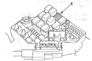
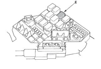
7. Test the A/F sensor relay (LAF) (E) in the under-hood fuse/relay box.
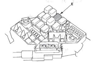
Is the A/F sensor relay (LAF) OK? YES-Go to step 8.
NO-Replace the A/F sensor relay (LAF), then go to step 24.
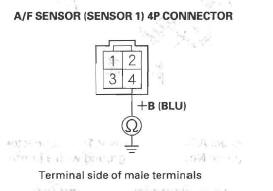
8. Disconnect the A/F sensor (Sensor 1) 4P connector.
9. At the sensor side, measure resistance between A/F sensor (Sensor 1) 4P connector terminals No.3 and No. 4.
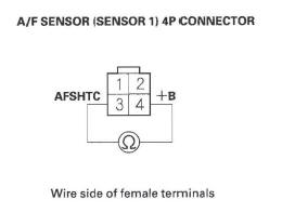
Is there 1.98- 2.42 Ω at room temperature? YES-Go to step 10.
NO-Go to step 24.
10. At the sensor side, check for continuity between A/F sensor (Sensor 1) 4P connector terminals No.1 and No.3, and between terminals No.1 and No.4 individually.
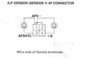
Is there continuity? YES-Go to step 24.
NO-Go to step 11.
11. Jump the SCS line with the HDS.
12. Disconnect PCM connector C (44P).
13. Connect A/F sensor (Sensor 1) 4P connector terminal No.3 to body ground with a jumper wire.
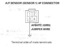
14. Check for continuity between PCM connector terminal C9 and body ground.
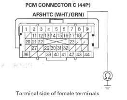
Is there continuity? YES-Go to step 15.
NO-Repair open in the wire between the PCM (C9) and the A/F sensor (Sensor 1), then go to step 25.
15. Remove the A/F sensor relay (LAF) (E) from the under-hood fuse/relay box.
16. Connect A/F sensor (Sensor 1) 4P connector terminal No.4 to body ground with a jumper wire.
17. Check for continuity between A/F sensor relay (LAF) 4P connector terminal No.2 and body ground.
Is there continuity? YES-Go to step 18.
NO-Repair open in the wire between the A/F sensor (Sensor 1) and the A/F sensor relay (LAF), then go to step 25.
18. Disconnect PCM connector A (44P).
19. Check for continuity between A/F sensor relay (LAF) 4P connector terminal No.3 and PCM connector terminal A21.
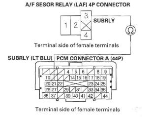
Is there continuity? YES-Go to step 31.
NO-Repair open in the wire between the PCM (A21) and the A/F sensor relay (LAF), then go to step 25.
20. Remove the A/F sensor relay (LAF) (E) from the under-hood fuse/relay box.
21. Disconnect the A/F sensor (Sensor 1) 4P connector.
22. Disconnect the EVAP canister vent shut valve 2P connector.
23. Check for continuity between A/F sensor (Sensor 1) 4P connector terminal No.4 and body ground.
Is there continuity? YES-Repair short in the wire between the A/F sensor relay (LAF), the EVAP canister vent shut valve, and the A/F sensor (Sensor 1). Also replace the No.1 1 + B LAF (A/F SENSOR) (15 A) fuse, then go to step 25.
NO-Replace the under-hood fuse/relay box, then go to step 25.
24. Replace the A/F sensor (Sensor 1).
25. Reconnect all connectors.
26. Turn the ignition switch ON (II).
27. Reset the PCM with the HDS.
28. Do the PCM idle learn procedure.
29. Check for Temporary DTCs or DTCs with the HDS.
Is DTC P0135 indicated? YES-Check for poor connections or loose terminals at the A/F sensor (Sensor 1), the A/F sensor relay (LAF), and the PCM, then go to step 1.
NO-Go to step 30.
30. Monitor the OBD STATUS for DTC P0135 in the DTCs MENU with the HDS.
Does the screen indicate PASSED? YES-Troubleshooting is complete. If. any other Temporary DTCs or DTCs were indicated in step 29, go to the indicated DTC's troubleshooting.
NO-If the screen indicates FAILED, check for poor connections or loose terminals at the A/F sensor (Sensor 1). the A/F sensor relay (LAF), and the PCM, then go to step 1. If the screen indicates NOT COMPLETED, go to step 28.
31. Reconnect all connectors.
32. Update the PCM if it does not have the latest software, or substitute a known-good PCM.
33. Start the engine.
34. Check for Temporary DTCs or DTCs with the HDS.
Is DTC P0135 indicated? YES-Check for poor connections or loose terminals at the A/F sensor (Sensor 1), the A/F sensor relay (LAF), and the PCM. If the PCM was updated, substitute a known-good PCM, then go to step 33. If the PCM was substituted, go to step 1.
NO-Go to step 35.
35. Monitor the OBD STATUS for DTC P0135 in the DTCs MENU with the HDS.
Does the screen indicate PASSED? YES-If the PCM was updated, troubleshooting is complete. If the PCM was substituted, replace the original PCM. If any other Temporary DTCs or DTCs were indicated in step 34, go to the indicated DTC's troubleshooting.
NO-If the screen indicates FAILED, check for poor connections or loose terminals at the A/F sensor (Sensor 1), the A/F sensor relay (LAF), and the PCM.
If the PCM was updated, substitute a known-good PCM, then go to step 34. If the PCM was substituted, go to step 1. If the screen indicates NOT COMPLETED, keep idling until a result comes on.
READ NEXT:
 DTC P0137: Secondary HO2S (Sensor 2)
Circuit Low Voltage
DTC P0137: Secondary HO2S (Sensor 2)
Circuit Low Voltage
NOTE: Before you troubleshoot, record all freeze data
and any on-board snapshot, and review the general
troubleshooting information.
1. Turn the ignition switch ON (II).
2. Clear the DTC with the HDS
DTC P0300: Random Misfire and Any Combination of the Following
DTC P0301: No.1 Cylinder Misfire Detected
DTC P0302: No.2 Cylinder Misfire Detected
DTC P0303: No.3 Cylinder Misfire Detected
DTC P0304: No.4 Cylinder Misfire Detected
Special Tools Required
Pressur
DTC P0325: Knock Sensor Circuit Malfunction
NOTE: Before you troubleshoot, record all freeze data and any on-board
snapshot, and review the general troubleshooting information.
1. Turn the ignition switch ON (II).
2. Clear the DTC with the HD
SEE MORE:
DTC 32-8x ("x" can be 0 thru 9 or A thru F):
Short to Power in Front Passenger's Side
Airbag Inflator
Special Tools Required
SRS inflator simulator 07SAZ-TB4011A
SRS simulator lead L 070AZ-SNAA300
NOTE: Before doing this troubleshooting procedure,
review SRS Precautions and Procedures.
1. Erase the DTC memory.
2. Turn the ignition switch ON (II), and check that the
SRS indicator comes on for a
Cam Chain Inspection
1. Remove the front wheels.
2. Remove the splash shield (see step 21).
3. Remove the drive belt.
4. Remove the cylinder head cover.
5. Set the No.1 piston at top dead center (TDC). The
punch mark on the variable valve timing control
(VTC) actuator and the punch mark on the exhaust
camshaft sproc
