Honda CR-V: Charging System Indicator Circuit Troubleshooting
1. Turn the ignition switch ON (II).
Does the charging system indicator come on? YES-Go to step 2.
NO-Go to step 14.
2. Start the engine. Hold the engine speed at 2,000 rpm for 1 minute.
Does the charging system indicator go off? YES-Charging system indicator circuit is OK. Go to the alternator and regulator circuit troubleshooting.
NO-Go to step 3.
3. Do the gauge control module self-diagnostic function procedure.
Does the charging system indicator flash? YES-Go to step 4.
NO-Replace the gauge control module.
4. Turn the ignition switch OFF.
5. Disconnect the alternator 4P connector.
6. Turn the ignition switch ON (II).
Does the charging system indicator go off? YES-Replace the alternator, or repair the alternator.
NO-Go to step 7.
7. Turn the ignition switch OFF.
8. Connect the Honda Diagnostic System (HDS) to the data link connector (DLC).
9. Turn the ignition switch ON (II).
10. Make sure the HDS communicates with the vehicle and the powertrain control module (PCM). If it doesn't communicate, troubleshoot the DLC circuit.
11. Jump the SCS line with the HDS, then turn the ignition switch OFF.
NOTE: This step must be done to protect the PCM from damage.
12. Disconnect PCM connector B (44P).
13. Check for continuity between PCM connector terminal B42 and body ground.
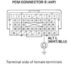
Is there continuity? YES-Repair short in the wire between the alternator and the PCM.
NO-Substitute a known-good PCM , then recheck. If the symptom/indication goes away with a known-good PCM, replace the original PCM.
14. Do the gauge control module self-diagnostic function procedure.
Does the charging system indicator flash? YES-Go to step 15.
NO-Replace the gauge control module.
15. Turn the ignition switch OFF.
16. Disconnect the alternator 4P connector.
17. Connect alternator 4P connector terminal No.3 to body ground with a jumper wire.
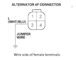
18. Turn the ignition switch ON (II).
Does the charging system indicator come on? YES-Replace the alternator , or repair the alternator.
NO-Leave the jumper connected from step 17, and go to step 19.
19. Connect the HDS to the DLC.
20. Turn the ignition switch ON (II).
21. Make sure the HDS communicates with the vehicle and the PCM. If it doesn't communicate, troubleshoot the DLC circuit.
22. Jump the SCS line with the HDS, then turn the ignition switch OFF.
NOTE: This step must be done to protect the PCM from damage.
23. Disconnect PCM connector B (44P).
24. Check for continuity between PCM connector terminal B42 and body ground.
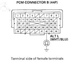
Is there continuity? YES-Substitute a known-good PCM , then recheck. If the symptom/indication goes away with a known-good PCM, replace the original PCM.
NO-Repair open in the wire between the alternator and the PCM.
READ NEXT:
 Alternator and Regulator
Circuit Troubleshooting
Alternator and Regulator
Circuit Troubleshooting
1. Make sure the battery connections are good and
the battery is sufficiently charged.
2. Connect a VAT-40 (or equivalent tester), and turn
the selector switch to position 1 (starting).
3. Start the
Drive Belt Inspection
1. Inspect the belt for cracks and damage. If the belt is
cracked or damaged, replace it.
2. Check that the auto-tensioner indicator (A) is within
the standard range (B) as shown. If it is out of the
Alternator Removal and
Installation
Removal
1. Make sure you have the anti-theft code for the
audio system and the navigation system (if
equipped), then write down the XM radio presets.
2. Disconnect the negative cable from the battery
SEE MORE:
To Load a Disc
The in-dash disc player is behind the
navigation screen. To use the disc
player, press the OPEN button
beside the screen. The screen folds
back, and the disc slot appears.
Insert a disc about halfway into the
disc slot. The drive will pull the disc
in the rest of the way and beg
Tailgate
The tailgate will lock when you lock
the driver’s door with the key, the
remote transmitter, the master door
lock switch, or the lock tab on the
driver’s door.
To unlock the tailgate, turn the key
clockwise twice, push the rear of the
master door lock switch, or push the
UNLOCK bu
