Honda CR-V: Alternator and Regulator Circuit Troubleshooting
1. Make sure the battery connections are good and the battery is sufficiently charged.
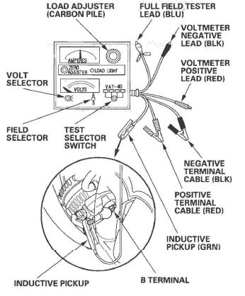
2. Connect a VAT-40 (or equivalent tester), and turn the selector switch to position 1 (starting).
3. Start the engine. Hold the engine speed at 3,000 rpm with no load until the radiator fan comes on, then let it idle.
4. Raise the engine speed to 2,000 rpm, and hold it there.
Is the voltage over 15.1 V? YES-Replace the alternator, or rear housing assembly.
NO-Go to step 5.
5. Release the accelerator pedal, and let the engine idle.
6. Make sure all accessories are turned off. Turn the selector switch to position 2 (charging).
7. Remove the inductive pickup, and zero the ammeter.
8. Place the inductive pickup over the B terminal wire of the alternator so the arrow points away from the alternator.
9. Raise the engine speed to 2,000 rpm, and hold it there.
Is the voltage less than 13.5 V? YES-Go to alternator control circuit troubleshooting.
NO-Go to step 10.
10. Apply a load with the VAT-40 until the battery voltage drops within 12-13.5 V.
Is the amperage 87.5 A or more? YES-The charging system is OK.
NOTE: If the charging system indicator is still on, replace the alternator.
NO-Replace the alternator, or repair the alternator.
Alternator Control Circuit Troubleshooting
1. Connect the Honda Diagnostic System (HDS) to the data link connector (DLC) (see step 2).
2. Turn the ignition switch ON (II).
3. Make sure the HDS communicates with the vehicle and the powertrain control module (PCM). If it doesn't, troubleshoot the DLC circuit.
4. Check for DTCs. If a DTC is present, diagnose and repair the cause before continuing with this test.
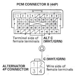
5. Disconnect the alternator 4P connector from the alternator.
6. Start the engine, and turn on the headlights to high beam.
7. Measure the voltage between alternator 4P connector terminal No.2 and the positive terminal of the battery.
Is there 1 V or less? YES-Go to step 11.
NO-Go to step 8.
8. Jump the SCS line with the HDS, then turn the ignition switch OFF.
NOTE: This step must be done to protect the PCM from damage.
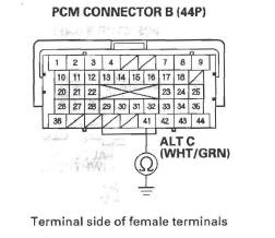
9. Disconnect PCM connector B (44P).
10. Check for continuity between PCM connector terminal B41 and body ground.
Is there continuity? YES-Repair short in the wire between the alternator and the PCM.
NO-Update the PCM if it does not have the latest software, then recheck. If the problem is still present substitute a known good PCM, then recheck. If the symptom/ indication goes away with a known-good PCM, replace the original PCM.
11. Jump the SCS line with the HDS, then turn the ignition switch OFF.
NOTE: This step must be done to protect the PCM from damage.
12. Disconnect PCM connector B (44P).
13. Check for continuity between PCM connector terminal B41 and alternator 4P connector terminal No.2.
Is there continuity? YES-Replace the alternator, or repair the alternator.
NO-Repair open in the wire between the alternator and the PCM.
READ NEXT:
 Drive Belt Inspection
1. Inspect the belt for cracks and damage. If the belt is
cracked or damaged, replace it.
2. Check that the auto-tensioner indicator (A) is within
the standard range (B) as shown. If it is out of the
Alternator Removal and
Installation
Removal
1. Make sure you have the anti-theft code for the
audio system and the navigation system (if
equipped), then write down the XM radio presets.
2. Disconnect the negative cable from the battery
Cruise Control
Component Location Index
CRUISE MAIN INDICATOR
CRUISE CONTROL INDICATOR
CRUISE CONTROL
COMBINATION SWITCH
BRAKE PEDAL POSITION SWITCH
POWERTRAIN CONTROL MODULE (PCM)
TRANSMISSION RANGE
SEE MORE:
DTC P2227: BARD Sensor Range/Performance Problem
NOTE:
Before you troubleshoot, record all freeze data and any on-board
snapshot, and review the general troubleshooting information.
If DTC P0101, P0108, P1128, and/or P1129 are stored
at the same time as DTC P2221, troubleshoot those
DTCs first, then recheck for DTC P2221.
1. Turn the ignit
DTC P0731: Problem in 1st Clutch and 1st
Clutch Hydraulic Circuit
NOTE: Before you troubleshoot, record all freeze data and any on-board
snapshot, and review General Troubleshooting Information.
1. Warm up the engine to normal operating
temperature (the radiator fan comes on).
2. Make sure that the transmission is filled to the
proper level, and check for fluid
