Honda CR-V: ATF Cooler
ATF Cooler Cleaning
Special Tools Required
- ATF cooler cleaner GHTTTCF6H
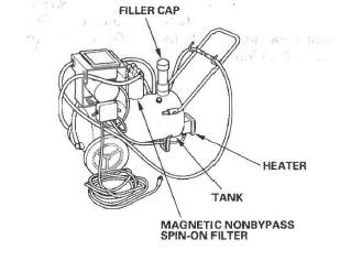
- Magnetic nonbypass spin-on filter GTHGNBP2
These special tools are available through the Honda Tool and Equipment Program 1-888-424-6857.
Before installing an overhauled or remanufactured automatic transmission, you must thoroughly clean the ATF cooler to prevent system contamination. Failure to do so could cause a repeat automatic transmission failure.
The cleaning procedure involves heated ATF-Zl delivered under high pressure (100 psi), Check the security of all hoses and connections. Always wear safety glasses or a face shield, along with gloves and protective clothing. If you get ATF in your eyes or on your skin, rinse with water immediately.
WARNING
- Improper use of the ATF cooler cleaner can result in burns and other serious injuries,
- Always wear eye protection and protective clothing, and follow this procedure.
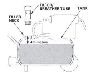
1. Check the fluid in the cooler cleaner tank. (The fluid level should be 4.5 inches from the top of the filler neck.) Adjust the level if needed; do not overfill.
Use only Honda ATF-Z1l; do not use any additives.
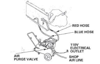
2. Plug the cooler cleaner into a 110 V grounded electrical outlet.
NOTICE
Make sure the outlet has no other appliances (light fixtures, drop lights, extension cords) plugged into it. Also, never plug the cooler cleaner into an extension cord or drop light; you could damage the unit.
3. Flip the HEAT toggle switch to ON; the green indicator above the toggle switch comes on. Wait 1 hour for the cooler cleaner to reach its operating temperature. (The cooler cleaner is ready to use when the temperature gauge reads 140 to 150 ºF)
NOTE: If the red indicator above the HEAT toggle switch comes on, the fluid level in the tank is too low for the tank heater to work (see step 1 of this procedure).
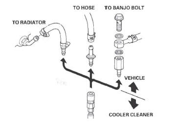
4. Select the appropriate pair of fittings, and attach them to the radiator, to the hoses, or to the banjo bolts for flow through the ATF cooler cleaner.
5. Connect the red hose to the cooler outlet line (the line that normally goes to the external filter on the transmission).
6. Connect the blue hose to the cooler inlet line.
7. Connect a shop air hose (regulated to 100 to 125 psi) to the air purge valve.
NOTICE
The quick-connect fitting has a one-way check valve to keep ATF from entering your shop's air system. Do not remove or replace the fitting. Attach the coupler provided with the cooler cleaner to your shop air line if your coupler is not compatible.
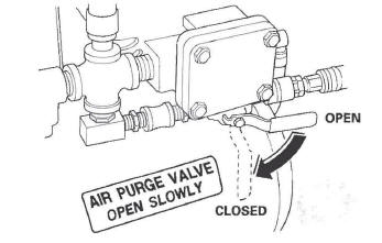
8. Flip the MOTOR toggle switch to ON; the green indicator above the toggle switch comes on. Let the pump run for 5 minutes. While the pump is running, open and close the air purge valve periodically to cause agitation and improve the cleaning process.
Always open the valve slowly. At the end of the 5-minutes cleaning period, leave the air purge valve open.
NOTE: While the pump is running with the air purge valve open, it is normal to see vapor coming from the filler/breather tube vents.
9. With the air purge valve open, flip the MOTOR toggle switch to OFF; the green indicator goes off.
Leave the air purge valve open for at least 15 seconds to purge the lines and hoses of residual ATF, then close the valve.
10. Disconnect the red and blue hoses from the ATF cooler. Now connect the red hose to the cooler inlet line.
11. Now connect the blue hose to the cooler outlet line.
12. Flip the MOTOR toggle switch to ON, and let the pump run for 5 minutes. While the pump is running, open and close the air purge valve periodically.
Always open the valve slowly. At the end of the 5-minutes cleaning period, leave the air purge valve open.
NOTE: While the pump is running with the air purge valve open, it is normal to see vapor coming from the filler/breather tube vents, 13. With the air purge valve open, flip the MOTOR toggle switch to OFF. Leave the air purge valve open for at least 15 seconds to purge the lines and hoses of residual ATF, then close the valve.
14. Disconnect the red and blue hoses from the ATF cooler lines.
15. Connect the red and blue hoses to each other.
16. Disconnect the shop air from the air purge valve.
Disconnect and stow the coupler if used.
17. Disconnect and stow the fittings from the ATF cooler inlet and outlet lines.
18. Unplug the cooler cleaner from the 110 V outlet.
Tool Maintenance
Follow these instructions to keep the ATF cooler cleaner working properly:
- Replace the two magnetic nonbypass spin-on filters once a year or when you notice a restriction in the ATF flow.
- Check the level and condition of the fluid in the tank before each use.
- Replace the ATF in the tank when it looks dark or dirty.
ATF Cooler Hose Replacement
1. Slide the ATF cooler/filter hose (A) on the ATF filter (B) until the hose end is 5-7 mm (0.20-0.28 in.) (C) away from the filter housing, and secure the hose with the clip (D) at 10-12 mm (0.39-0.47 in.) (E) from the filter housing. Install the cooler hose (F) on the other side of the ATF filter in the same manner.
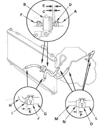
2. Slide the ATF cooler/filter hose (G) over the ATF cooler line (H) until the hose end contacts the bulge (I), and secure the hoses with the clip (J) at 2-4 mm (0.08-0.16 in.) (K) from the hose end.
3. Slide the ATF cooler hoses (L) over the ATF lines (M) until the hose ends contact the bulge (N), and secure the hoses with the clip (O) at 6-8 mm (0.24-0.31 in.) (P) from the hose end.
ATF Filter Replacement
NOTE: The ATF filter is not a scheduled maintenance item. Replace the filter only if it is leaking, or contaminated, or when the transmission is being overhauled or replaced with a remanufactured unit.
1. Raise the vehicle on a lift, or apply the parking brake, block the rear wheels, and raise the front of the vehicle. Make sure it is securely supported.
2. Remove the splash shield.
3. Remove the drain plug (A), and drain the transmission fluid (ATF).
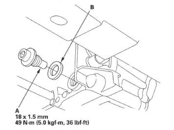
4. Reinstall the drain plug with the new sealing washer (B).
5. Disconnect the ATF cooler hoses (A) from the ATF filter (B).
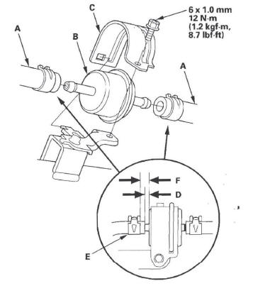
6. Remove the ATF filter holder (C), and remove the ATF filter.
7. Install the new ATF filter, and secure it with its holder and bolt.
8. Slide the ATF cooler hose on the ATF filter until the hose end is 5-7 mm (0.20-0.28 in.) (D) away from the filter housing, and secure the hose with the clip (E) at 10-12 mm (0.39-0.47 in.) (F) from the filter housing. Install the cooler hose on the other side of the ATF filter in the same manner.
9. Install the splash shield.
10. Refill the transmission with ATF (see step 5).
READ NEXT:
 Shift Lever
Shift Lever Removal
1. Remove the following parts:
Heater control panel
Dashboard center panel
Center lower covers
2. Shift the shift lever into the R position.
3. Remove the nut securing the s
Shift Cable
Shift Cable Replacement
1. Lift the vehicle up on a lift or apply the parking
brake, block rear wheels, and raise the *front of the
vehicle. Make sure it is securely supported.
2. Remove the followin
A/T Gear Position Indicator
Component Location Index
A/T GEAR POSITION INDICATOR
F-CAN Communication Circuit Troubleshooting
Gauge Control Module Self-diagnostic Function Indicator Drive Circuit
Check
Communication Line
SEE MORE:
DTC 86: F-CAN Communication
1. Turn the ignition switch ON (II).
2. Clear the DTC with the HDS.
3. Turn the ignition switch OFF.
4. Start the engine.
5. Wait at least 5 seconds.
6. Check for DTCs with the HDS.
Is DTC 86 indicated?
YES-Go to step 7.
NO-Intermittent failure, the system is OK at this time. Check for a loos
DTC 12, 14, 16, 18: Wheel Sensor (Electrical
Noise/Intermittent Interruption)
NOTE:
If the ABS and other indicators come on because of
electrical noise, the indicators will go off when you
test-drive the vehicle at 10 mph (15 km/h) or more
and noise is gone.
An incorrectly installed wheel bearing can cause one
of these DTCs.
1. Turn the ignition switch OFF.
2. Check
