Honda CR-V: A/C Signal Circuit Troubleshooting
1. Start the engine, and let it idle.
2. Turn the blower switch on.
3. Turn the A/C switch on.
4. Check the A/C CLUTCH in the DATA LIST with the HDS.
Does it indicate ON? YES-Go to step 5.
5. Check the A/C system.
Does the A/C system operate? YES-The air conditioning system circuit is OK.
NO-Go to step 6.
6. Turn the ignition switch OFF.
7. Turn the ignition switch ON (II).
8. Activate the A/C CLUTCH in the INSPECTION MENU with the HDS.
Is there a clicking noise from the Ale compressor clutch? YES-Do the A/C system test.
NO-Go to step 9.
9. Turn the ignition switch OFF.
10. Jump the SCS line with the HDS.
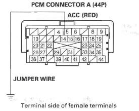
11. Disconnect PCM connector A (44P).
12. Turn the ignition switch ON (II).
13. Momentarily connect PCM connector terminal A14 to body ground with a jumper wire several times.
Is there a clicking noise from the Ale compressor clutch? YES-Update the PCM if it does not have the latest software, or substitute a known-good PCM, then recheck. If the symptom/indication goes away with a known-good PCM, replace the original PCM.
NO-Check for poor connections or loose terminals at the A/C compressor clutch relay and the PCM. If the connections are OK, check the A/C compressor clutch relay. Then repair open in the wire between the PCM (A 14) and the A/C compressor clutch relay and the other A/C systems.
Alternator FR Signal Circuit Troubleshooting
1. Start the engine, and let it idle.
2. Monitor the ALTERNATOR in the DATA LIST with the HDS.
3. Check if the indicated percentage varies when the headlight switch is turned on.
Does the percentage vary? YES-The alternator signal circuit is OK.
NO-Go to step 4.
4. Turn the headlight switch and ignition switch OFF.
5. Jump the SCS line with the HDS.
6. Disconnect the alternator 4P connector.
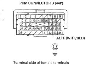
7. Disconnect PCM connector B (44P).
8. Check for continuity between body ground and PCM connector terminal B43.
Is there continuity? YES-Repair short in the wire between the PCM (B43) and the alternator.
NO-Update the PCM if it does not have the latest software, or substitute a known-good PCM, then recheck. If the symptom/indication goes away with a known-good PCM, replace the original PCM.
READ NEXT:
 PSP Switch Signal Circuit Troubleshooting
1. Start the engine, and let it idle.
2. Align the steering wheel straight ahead.
3. Check the PSP SWITCH in the DATA LIST with the
HDS.
Does it indicate ON?
YES-Go to step 4.
NO-Go to step 14.
4.
Brake Pedal Position Switch Signal Circuit Troubleshooting
1. Turn the ignition switch ON (II).
2. Check the BRAKE SWITCH in the DATA LIST with
the HDS.
Does it indicate OFF?
YES-Go to step 3.
NO-Inspect the brake pedal position switch.
3. Press the brake
Fuel Supply System
Component Location Index
FUEL RAIL
FUEL FEED LINE
FUEL TANK
FUEL TANK UNIT
FUEL PUMP
FUEL GAUGE SENDING UNIT
FUEL PRESSURE REGULATOR
FUEL FILTER
FUEL FI
SEE MORE:
Blower Unit
Removal/Installation
1. Remove the glove box.
2. Disconnect the connector (A), then remove the
connector clip (B), the wire harness clips (C), the
bolts, and the glove box frame (D).
3. Cut the plastic cross brace (A) in the glove box
opening with diagonal cutters in the area shown.
Retain plastic cross brace to be r
Troubleshooting
Troubleshooting - B-CAN System
Diagnosis Test Mode A
Check the PCM for DTCs, and troubleshoot PCM or F-CAN loss of communication errors
first, then do this diagnosis if the symptom is related to
the B-CAN system.
NOTE: Always cycle the ignition switch within
3 seconds when prompted in the DTC troub
