Honda CR-V: Transmission End Cover
End Cover Removal
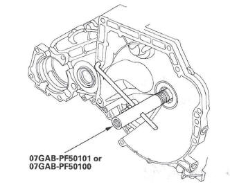
Special Tools Required
Mainshaft holder 07GAB-PF50101 or 07GAB-PF50100
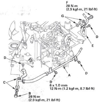
NOTE: The illustration shows the 4WD transmission; the 2WD is similar.
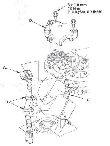
1. Remove the cooler inlet line bolt (D), sealing washers, and line bracket bolts (E), and remove the ATF cooler inlet line (F).
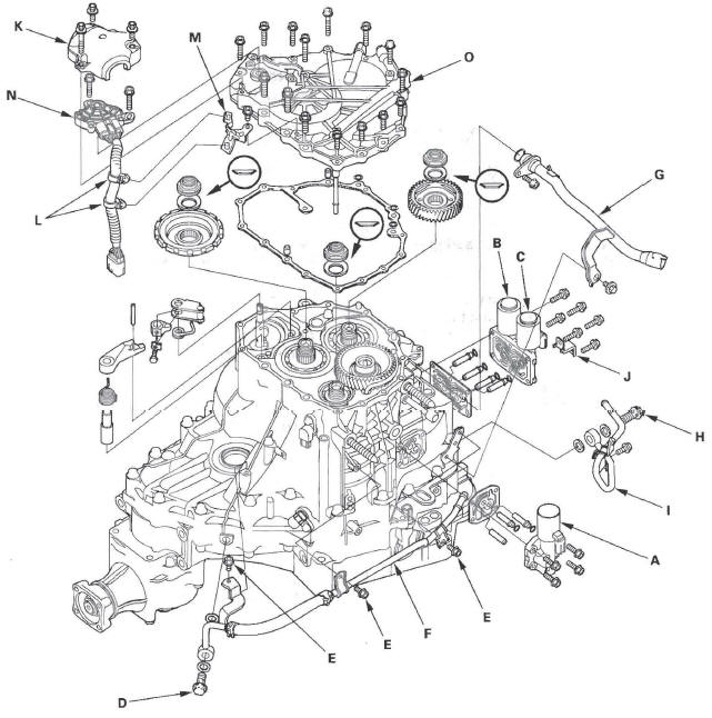
2. Remove the ATF dipstick guide tube (G).
3. Remove the cooler outlet line bolt (H) and sealing washers, and remove the ATF cooler outlet line (I).
4. Remove A/T clutch pressure control solenoid valve A, ATF joint pipes, O-rings, ATF pipe, and gasket.
5. Remove A/T clutch pressure control solenoid valve B and C, harness clamp bracket (J), ATF joint pipes, O-rings, and gasket.
6. Remove the transmission range switch cover (K).
7. Remove the transmission range switch harness clamps (L) from the clamp bracket (M), and remove the transmission range switch (N).
8. Remove the harness clamp bracket from the end cover (O).
9. Remove the end cover, dowel pins, O-rings, and end cover gasket.
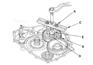
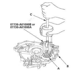
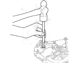
10. Slip the mainshaft holder onto the mainshaft.
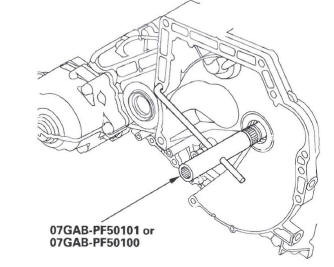
11. Engage the park pawl with the park gear.
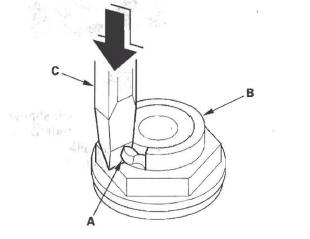
12. Cut the lock tab (A) of the each shaft locknut (B) using a chisel (C). Then remove the locknuts and conical spring washers from each shaft.
NOTE:
- Countershaft and secondary shaft locknuts have left-hand threads.
- Keep all of the chiseled particles out of the transmission.
- Clean the old mainshaft and countershaft locknuts; they are used to install the press fit idler gear on the mainshaft, and park gear on the countershaft.
13. Remove the special tool from the mainshaft.
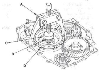
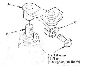
14. Set a two-jaw (or three-jaw) puller (A) on the countershaft (B) by putting a spacer (C) between the puller and countershaft, then remove the park gear (D).
15. Install a 6 x 1.0 mm bolts (A) on the mainshaft idler gear (B). Set a puller (C) on the mainshaft (D) with putting a spacer (E) between the puller and mainshaft, then remove the mainshaft idler gear.
16. Remove the park pawl, park pawl spring, park pawl shaft, and stop shaft.
17. Remove the park lever from the control shaft.
Park Lever Stop Inspection and Adjustment
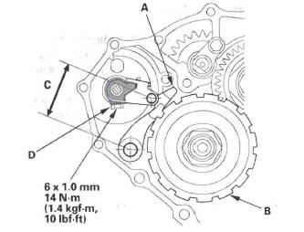
1. Set the park lever in the P position.
2. Measure the distance (A) between the park pawl shaft (B) and the park lever roller pin (C).
Standard: 57.7-58.7 mm (2.27-2.31 in.)
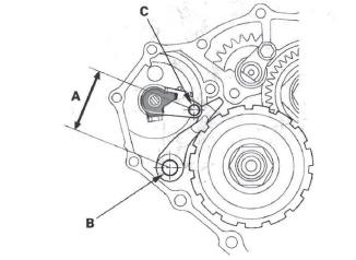
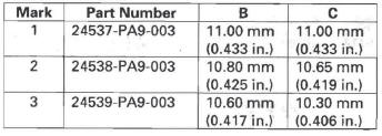
3. If the measurement is out of standard, select and install the appropriate park lever stop (A) from the table.
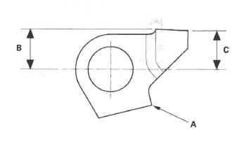
PARK LEVER STOP
4. After replacing the park lever stop, make sure the distance is within tolerance.
Idler Gear Shaft Bearing Replacement
Special Tools Required
- Adjustable bearing puller, 25-40 mm 07736-A01000B or 07736-A01000A
- Driver 07749-0010000
- Attachment, 52 x 55 mm 07746-0010400
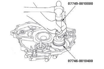
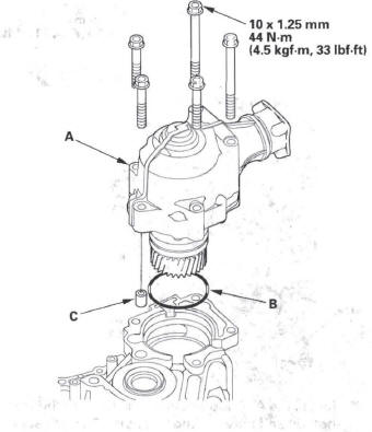
1. Remove the idler gear shaft bearing (A) from the end cover (B) using the adjustable bearing puller and a commercially available 3/8 " -16 slide hammer (C).
2. Install the new bearing in the end cover using the driver and the attachment (52 x 55 mm).
Selector Control Shaft Oil Seal Replacement
Special Tools Required
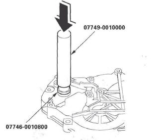
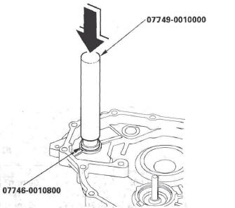
- Driver 07749-0010000
- Attachment, 22 x 24 mm 07746-0010800
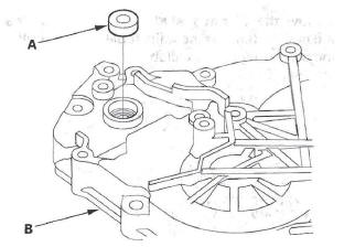
1. Remove the oil seal (A) from the end cover (B).
2. Install the new oil seal flush to the end cover using the driver and the attachment (22 x 24 mm).
Selector Control Shaft Bearing Replacement
Special Tools Required
- Driver 07749-0010000
- Attachment, 22 x 24 mm 07746-0010800
1. Remove the oil seal from the end cover, then remove the bearing.
2. Install the new bearing flush to the end cover using the driver and the attachment (22 x 24 mm).
3. Install the new oil seal.
ATF Feed Pipe Replacement
1. Remove the snap rings (A), ATF feed pipes (B), and feed pipe flanges (C) from the end cover (D).
NOTE: Replace the end cover, if the 1st clutch ATF feed pipe (E) replacement is required.
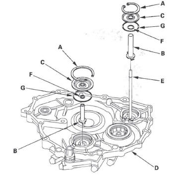
2. Install the new O-rings (F) over the ATF feed pipes.
3. Install the ATF feed pipes in the end cover by aligning the feed pipe tabs with the indentations in the end cover.
4. Install the new O-rings (G) in the end cover, then install the feed pipe flanges over the ATF feed pipes.
5. Secure the ATF feed pipes and feed pipe flanges with the snap rings.
End Cover Installation
Special Tool Required
Mainshaft holder 07GAB-PF50101 or 07GAB-PF50100
1. Install the mainshaft holder onto the mainshaft.
2. Lubricate the following parts with ATF:
- Splines and threads of the mainshaft.
- Splines of the mainshaft idler gear.
- Old conical spring washer and old locknut.
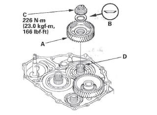
3. Install the mainshaft idler gear (A), old conical spring washer (B), and old locknut (C) on the mainshaft (D), and tighten the locknut to 226 N*m (23.0 kgf*m, 166Ibf*ft).
NOTE:
- Do not tap the idler gear to install.
- Use a torque wrench to tighten the locknut. Do not use an impact wrench.
4. Install the park lever (A) and park lever stop (B) on the selector control shaft (C), then install the lock bolt with the new lock washer (D). Do not bend the lock tab of the lock washer until step 18.
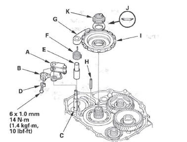
5. Install the park pawl shaft (E), park pawl spring (F), park pawl (G), and stop shaft (H) on the transmission housing.
6. Lubricate the following parts with ATF:
- Threads and splines of the countershaft.
- Old conical spring washer and old locknut.
- Areas where the park gear contacts the conical spring washer.
7. Install the park gear (I), old conical spring washer (J), and old locknut (K) on the countershaft.
8. Lift the park pawl up, and engage it with the park gear, then tighten the locknut to 226 N*m (23.0 kgf*m, 166 Ibf*ft).
NOTE:
- Do not tap the park gear to install.
- Use a torque wrench to tighten the locknut. Do not use an impact wrench.
- Countershaft locknut has left-hand threads.
9. Remove the locknuts and conical spring washers from the mainshaft and countershaft.
10. Lubricate the threads of the shafts, the new locknuts and the new conical spring washers with ATF.
11. Install the new conical spring washers (A) with facing stamped mark side up in the direction shown, and install the new mainshaft locknut (B), the new countershaft locknut (C), and the new secondary shaft locknut (D).
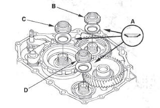
12. Tighten the locknuts to 167 N*m (17.0 kgf*m, 123 Ibf*ft).
NOTE:
- Be sure to install the conical spring washers in the direction shown.
- Use a torque wrench to tighten the locknut. Do not use an impact wrench.
- Countershaft and secondary shaft locknuts have left-hand threads.
13. Remove the special tool from the mainshaft.
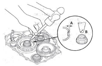
14. Stake the locknuts into the shafts in depth (A) of 0.7-1.3 mm (0.03 - 0.05 in.) using a 3.5 mm punch (B).
15. Install the selector control level (A) on the selector control shaft (B), and install the bolt with the new lock washer (C), then bend the lock tab of the lock washer against the bolt head.
16. Set the park lever in the P position, then verify that the park pawl (A) engages the park gear (B).
17. If the park pawl does not engage fully, check the distance (C) between the pawl shaft and the park lever roller pin.
18. Tighten the lock bolt, and bend the lock tab of the lock washer (D) against the bolt head.
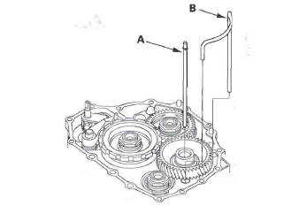
19. Install the ATF feed pipe (A) into the idler gear shaft, and install the ATF lubrication pipe (B) into the transmission housing.
20. Install the new gasket (A) on the transmission housing, and install the two dowel pins (B) and new O-rings (C) over the top of the ATF feed pipes.
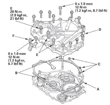
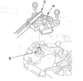
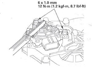
21. Install the end cover (D), and tighten the three special bolts (E) and the 6 x 1.0 mm bolts (12 bolts).
22. Install the harness clamp bracket (F) on the end cover.
23. Set the selector control shaft (A) to the N position by turning the selector control lever on the torque converter side.
NOTE: Do not squeeze the end of the selector control shaft tips together when turning the shaft. If the tips are squeezed together it will cause a faulty shift position signal or position due to the play between the selector control shaft and the transmission range switch.
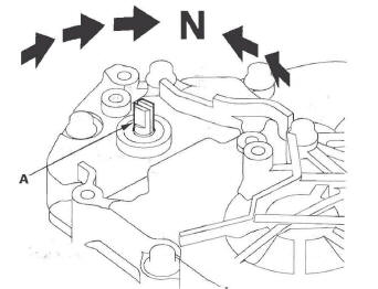
24. Align the cutouts (A) on the control shaft with the neutral positioning cutouts (B) on the transmission range switch (C), then put a 2.0 mm (0.08 in.) feeler gauge blade (D) in the cutouts to hold in the N position.
NOTE: Be sure to use a 2.0 mm (0.08 in.) blade or equivalent to hold the switch in the N position.
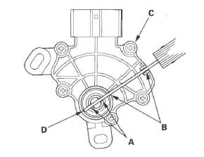
25. Install the transmission range switch (A) gently on the selector control shaft (B) while holding it in the N position with the 2.0 mm (0.08 in.) blade (C).
26. Tighten the bolts on the transmission range switch while you continue to hold it in the N position. Do not move the transmission range switch when tightening the bolts. Remove the feeler gauge.
27. Connect the transmission range switch connector (A) securely, then install the harness clamps (B) on the clamp bracket (C).
28. Install the transmission range switch cover (D).
29. Install the new gasket (B) on the transmission housing, and install the ATF pipe (C) and the ATF joint pipes (D).
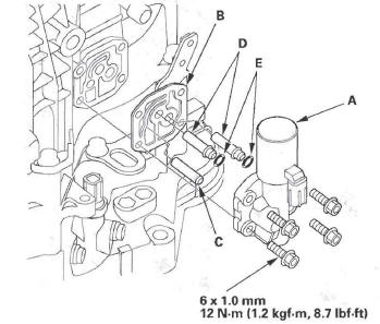
30. Install the new O-rings (E) over the ATF joint pipes, and install A/T clutch pressure control solenoid valve A.
31. Install the new gasket (A) and the ATF joint pipes (D) on the transmission housing, and install the new O-rings (E) over the ATF joint pipes.
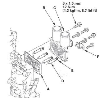
32. Install A/T clutch pressure control solenoid valve B and C, and the harness clamp bracket (F).
33. Install the new O-ring (A) on the dipstick guide tube (B), then install the dipstick guide tube.
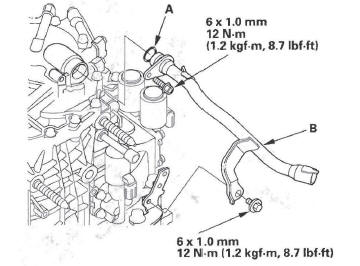
34. Install the ATF cooler inlet line (A) with the line bolt (B) and new sealing washers (C), and secure the inlet line with the bolts (D) on the transmission.
35. Install the ATF cooler outlet line (E) with the line bolt (F) and new sealing washers (G), and secure the outlet line with the bolt on the transmission.
36. Install the breather cap (A) on the breather pipe (B).
37. 4WD model: Install the transfer assembly (A) with the new O-ring (B) and dowel pin (C).
READ NEXT:
 Transmission Housing
Housing and Shaft Assembly Removal
NOTE: The illustration shows the 4WD transmission; the 2WD does not have the
transfer mechanism.
1. Remove the ATF feed pipe (A) from the idler gear shaft, and the
Valve Body
Valve Body and ATF Strainer Removal
NOTE: The illustration shows the 4WD transmission; the 2WD is similar.
1. Remove the ATF feed pipes (A) and ATF joint pipes (B).
2. Remove the ATF strainer (C) (t
Torque Converter Housing
Mainshaft Bearing and Oil Seal
Replacement
Special Tools Required
Adjustable bearing puller, 25-40 mm
07736-A01000B or 07736-A01000A
Attachment, 62 x 68 mm 07746-0010500
Attachment, 72 x 75 mm 0
SEE MORE:
Important Maintenance Precautions
If you have the required service
done but do not reset the display, or
reset the display without doing the
service, the system will not show the
correct maintenance intervals. This
can lead to seriousmechanical
problems because you will no longer
have an accurate record of when
maint
Playing the XM Radio (EX-L model with navigation system)
Playing the XM Radio (EX-L model with navigation system)
Your vehicle is capable of receiving
XM Radio anywhere in the United
States and Canada, except Hawaii,
Alaska, and Puerto Rico. XM is a
registered trademark of Sirius XM
Radio , Inc. and XMCANADA is a
registered business name
