Honda CR-V: Power switch will not turn ON (No information display and no sound) (with navigation)
1. With the ignition switch ON (II), push the power switch ON to see if navigation unit turns ON.
Does the navigation unit display operate properly, and does the audio sound normal? YES-Intermittent failure, the system is OK at this time.
NO-Go to step 2.
2. Turn the ignition switch OFF.
3. Check the No. 17 (15 A) fuse and the No. 23 (10 A) fuse in the under-hood fuse/relay box and No. 34 (7.5 A) fuse in the under-dash fuse/relay box.
Are the fuses OK? YES-Go to step 4.
NO-Replace the fuse(s), and recheck.
4. Remove the navigation unit.
Check that the navigation unit is properly connected.
Is it connected properly? YES-Go to step 5.
NO-Reconnect the connectors, and recheck the function.
5. Turn the ignition switch ON (II).
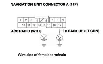
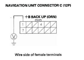
6. Measure the voltage between navigation unit connector A (17P) terminal No. 14 and body ground, and between terminal No. 17 and body ground, and navigation unit connector C (12P) No.1 terminal and body ground.
Is there battery voltage on both terminals? YES-Go to step 7.
NO-Repair open in the wire(s) between the No. 17 (15 A) fuse in the under-hood fuse/relay box and No. 34 (7.5 A) in the under-dash fuse/relay box and the audio unit.
7. Measure the voltage between navigation unit connector A (17P) No.9 terminal and body ground, navigation unit connector C (12P) No.4 terminal and body ground, and navigation unit connector B (22P) terminal No. 15 and body ground.
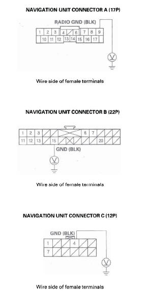
Is there less than 0.1 V on both terminals? YES-Replace the navigation unit.
NO-Repair open or high resistance in the wire between navigation unit connector A (17P) No.9 terminal or navigation unit connector B (22P) No. 15 terminal and body ground (G502), or navigation connector C (12P) and body ground (G504),
Power switch will not turn ON (No information display and no sound) (without navigation)
1. With the ignition switch ON (II), push the power switch ON to see if audio unit turns ON.
Does the audio unit operate properly, and does the audio sound normal? YES-Intermittent failure, the system is OK at this time.
NO-Go to step 2.
2. Turn the ignition switch OFF.
3. Check the No. 23 (10 A) fuse in the under-hood fuse/relay box and No. 34 (7.5 A) fuse in the under-dash fuse/relay box.
Are the fuses OK? YES-Go to step 4.
NO-Replace the fuse(s), and recheck.
4. Remove the audio unit. Check that the audio unit is properly connected.
Is it connected properly? YES-Go to step 5.
NO-Reconnect the connector, and recheck the function.
5. Turn the ignition switch ON (II).
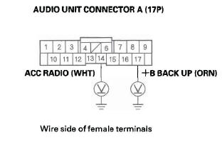
6. Measure the voltage between audio unit connector A (17P) termina1 No.14 and body ground, and between terminal No. 17 and body ground.
Is there battery voltage on the both terminals? YES-Go to step 7.
NO-Repair open in the wire(s) between the No. 23 (10 A) fuse in the under-hood fuse/relay box and No. 34 (7.5 A) in the under-dash fuse/relay box and the audio unit.
7. Measure the voltage between audio unit connector A (17P) No.9 terminal and body ground.
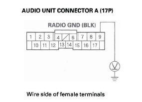
Is there less than 0.1 V? YES-Replace the audio unit.
NO-Repair open or high resistance in the wire between audio unit connector A (17P) No.9 terminal and body ground (G504).
Power will not turn OFF (with navigation)
1. With the ignition switch ON (II), push the power switch OFF or turn the ignition switch OFF to see if the navigation unit turns OFF.
Is the navigation unit OFF? YES-Operation is normal at this time.
NO-Go to step 2.
2. Turn the ignition switch OFF.
3. Remove the navigation unit.
Disconnect navigation unit connector A (17P).
4. Measure the voltage between navigation unit connector A (17P) terminal No. 14 and body ground.
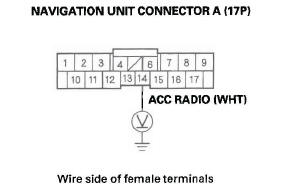
Is there voltage? YES-Check for short to power on WHT wire.
NO-Replace the navigation unit.
Power will not turn OFF (without navigation)
1. With the ignition switch ON (II), push the power switch. OFF or turn the ignition switch OFF to see if the audio unit turns OFF.
Is the audio unit OFF? YES-Operation is normal at this time.
NO-Go to step 2.
2. Turn the ignition switch OFF.
3. Remove the audio unit.
Disconnect audio unit connector A (17P).
4. Measure the voltage between audio unit connector A (17P) terminal No. 14 and body ground.
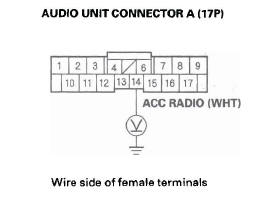
Is there voltage? YES-Check for short to power on WHT wire.
NO-Replace the audio unit.
READ NEXT:
 No sound is heard from speaker(s) (display is
normal) (with navigation)
No sound is heard from speaker(s) (display is
normal) (with navigation)
NOTE:
Set the fader and balance positions to the center.
Before doing symptom troubleshooting, do the
power switch will not turn ON troubleshooting.
1. Check that the volume button is not set to
Audio system sound is weak or distorted
(display is normal)
1. Check for sound in each mode (AM, FM, XM, and
disc).
Is there sound from the speakers, and is the sound quality normal in each mode?
YES-Intermittent failure. The system is OK at this time. Check
XM radio display is blank and no station
information is displayed
1. Disconnect audio disc changer 13P connector.
2. Turn the ignition switch to ACC (I).
3. Operate the XM radio, and check the display.
Is XM information displayed? YES-Replace the audio disc chang
SEE MORE:
DTC 71-2x ("x" can be 0 thru 9 or A thru F):
Short in Driver's Seat Position Sensor
NOTE: Before doing this troubleshooting procedure,
review SRS Precautions and Procedures.
1. Erase the DTC memory.
2. Turn the ignition switch ON (II), and check that the
SRS indicator comes on for about 6 seconds and
then goes off.
Does the SRS indicator stay on, and is DTC 71-2x
indicated?
YES-G
XM radio display is blank and no station
information is displayed
1. Disconnect audio disc changer 13P connector.
2. Turn the ignition switch to ACC (I).
3. Operate the XM radio, and check the display.
Is XM information displayed? YES-Replace the audio disc changer.
NO-Go to step 4.
4. Check the No. 34 (7.5 A) fuse in the under-dash
fuse/relay box and the No.
