Honda CR-V: Piston Ring Replacement
1. Remove the piston from the engine block.
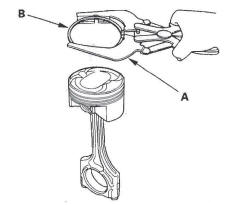
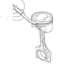
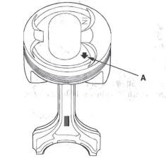
2. Using a ring expander (A), remove the old piston rings (B).
3. Clean all ring grooves thoroughly with a squared-off broken ring or ring groove cleaner with a blade to fit the piston grooves.
The top and 2nd ring grooves are 1.2 mm (0.05 in.) wide. The oil ring groove is 2.0 mm (0.08 in.) wide.
File down a blade if necessary.
Do not use a wire brush to clean the ring grooves, or cut the ring grooves deeper with the cleaning tools.
NOTE: If the piston is to be separated from the connecting rod, do not install new rings yet.
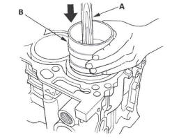
4. Using a piston that has its rings removed, push a new ring (A) into the cylinder bore 15-20 mm (0.6-0.8 in.) from the bottom.
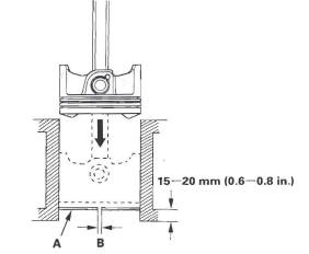
5. Measure the piston ring end-gap (B) with a feeler gauge:
- If the gap is too small, check to see if you have the proper rings for your engine.
- If the gap is too large, recheck the cylinder bore diameter against the
wear limits.
If the bore is beyond the service limit, the engine block must be rebored.
Piston Ring End-Gap
Top Ring:
Standard (New): 0.20-0.35 mm
(0.008-0.014 in.)
Service Limit: 0.60 mm (0.024 in.)
Second Ring:
Standard (New): 0.40-0.55 mm
(0.016-0.022 in.)
Service Limit: 0.70 mm (0.028 in.)
Oil Ring:
Standard (New): 0.25-0.65 mm
(0.010-0.026 in.)
Service Limit: 0.75 mm (0.030 in.)
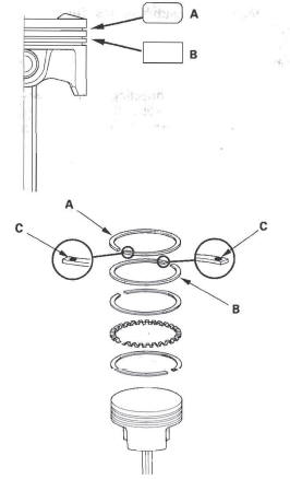
6. Install the top ring and the second ring as shown.
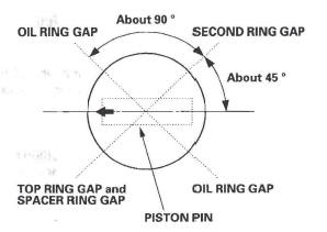
The top ring (A) has a 1 R mark, and the second ring (B) has a 2R mark. The manufacturing marks (C) must be facing upward.
Piston Ring Dimensions
Top Ring (Standard):
- 3.1 mm (0.12 in.)
- 1.2 mm (0.05 in.)
Top Ring (Standard):
- 3.1 mm (0.12 in.)
- 1.2 mm (0.05 in.)
7. Rotate the rings in their grooves to make sure they do not bind.
8. Position the ring end gaps as shown:
9. After installing a new set of rings, measure the ring-to-groove clearances:
Top Ring Clearance
Standard (New): 0.035-0.060 mm
(0.0014-0.0024 in.)
Service Limit: 0.13 mm (0.005 in.)
Second Ring Clearance
Standard (New): 0.030-0.055 mm
(0.0012-0.0022 in.)
Service Limit: 0.13 mm (0.005 in.)
Piston Installation
If the Crankshaft is Already Installed
1. Set the crankshaft to bottom dead center (BDC) for each cylinder as its piston is installed.
2. Remove the connecting rod caps, then install the ring compressor. Check that the bearing is securely in place.
3. Apply new engine oil to the piston, inside of the ring compressor, and the cylinder bore, then attach the ring compressor to the piston/connecting rod assembly.
4. Position the mark (A) to face the cam chain side of the engine.

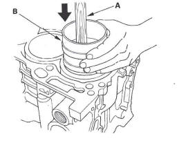
5. Position the piston in the cylinder, and tap it in using the wooden handle of a hammer (A).
Push down on the ring compressor (B) to prevent the rings from expanding before entering the cylinder bore.
6. Stop after the ring compressor pops free, and check the connecting rod-to-crank journal alignment before pushing the piston into place.
7. Check the connecting rod bearing clearance with plastigage.
8. Inspect the connecting rod bolts.
9. Install the rod caps with bearings. Torque the bolts to 20 N*m (2.0 kgf*m, 14Ibf*ft).
10. Tighten the connecting rod bolts an additional 90 º.
NOTE: Remove the connecting rod bolt if you tightened it beyond the specified angle, and go back to step 8 of the procedure. Do not loosen it back to the specified angle.
If the Crankshaft is Not Installed
1. Remove the connecting rod caps, then install the ring compressor, and check that the bearing is securely in place.
2. Apply new engine oil to the piston, inside of the ring compressor, and the cylinder bore, then attach the ring compressor to the piston/connecting rod assembly.
3. Position the mark (A) to face the cam chain side of the engine.
4. Position the piston in the cylinder, and tap it in' using the wooden handle of a hammer (A).
Push down on the ring compressor (B) to prevent the rings from expanding before entering the cylinder bore.
5. Position all pistons at top dead center (TDC).
Connecting Rod Bolt Inspection
1. Measure the diameter of each connecting rod bolt at point A and point B.
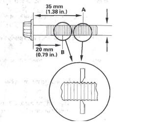
2. Calculate the difference in diameter between point A and point B.
Point A-Point B = Difference in Diameter
Difference in Diameter
Specification: 0-0.1 mm (0-0.004 in.)
3. If the difference in diameter is out of specification, replace the connecting rod bolt.
READ NEXT:
 Crankshaft Installation
Special Tools Required
Driver 077 49-00 10000
Oil seal driver attachment, 96 mm 07ZAD-PNAA.100
1. Check the connecting rod bearing clearance with
plastigage.
2. Check the main bearing clearance w
Oil Pan Installation
1. Remove all of the old liquid gasket from the oil pan
mating surfaces, bolts, and bolt holes.
2. Clean and dry the oil pan mating surfaces.
3. Apply liquid gasket, P/N 08717-0004,08718-0001,
08718
Engine Lubrication
Special Tools
Oil Filter Wrench
Component Location Index
OIL PAN
WASHER
DRAIN BOLT
OIL PUMP
OIL PUMP CHAIN
GUIDE
OIL PUMP CHAIN
TENSIONER
OIL CONTROL ORIFICE
OIL FIL
SEE MORE:
Damper/Spring
Damper/Spring Removal and Installation
Removal
1. Raise the rear of the vehicle, and support it with safety stands in the
proper locations.
2. Remove the rear wheel.
3. Remove the lid (A) on the cargo area side trim
panel by releasing the hooks (B).
4. Remove the flange nuts (C) from the top o
DTC 45-1x ("x" can be 0 thru 9 or A thru F):
No Signal From the Left Side Impact Sensor
(second)
Special Tools Required
SRS inflator simulator 07SAZ-TB4011A
SRS simulator lead L 070AZ-SNAA300
NOTE: Before doing this troubleshooting procedure, review SRS Precautions and
Procedures.
1. Erase the DTC memory.
2. Turn the ignition switch ON (II), and wait for
10 seconds.
3. Read the DTC.
Is
