Honda CR-V: Differential Mount Replacement
Exploded View
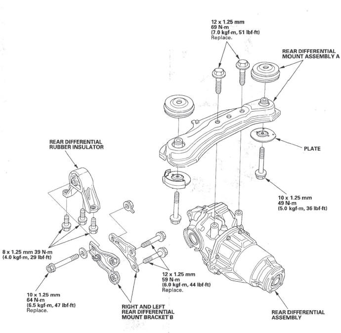
Differential Installation
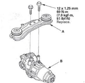
1. Install rear differential mount assembly A to the rear differential assembly (B).
2. Jack up the rear differential.
3. Install the new set rings (A) onto the driveshafts, then insert the drives hafts into the rear differential.
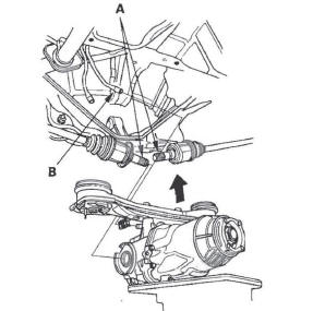
4. Lift the rear differential up into position, then push on both driveshafts to lock the set rings into place.
Connect the breather tube (B).
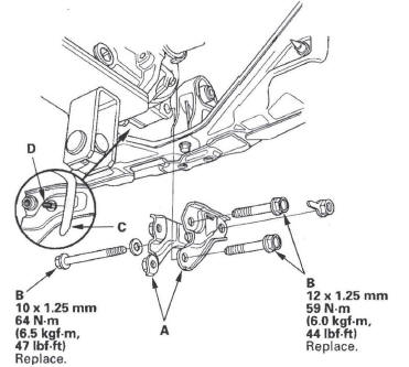
5. Align the tab (A) of the rubber mount (B) with the hole (C) of the plates (D), then install the plates and torque the rear differential mount assembly mounting bolts (E).
NOTE: The rubber heat insulator (F) is installed only in the right side.
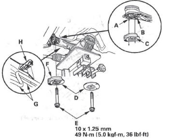
6. Install the breather tubes (G) to the clips (H).
7. Install the right and left rear differential mount brackets B (A), then torque the bolts (B).
8. Install the breather tube (C) to the clip (D).
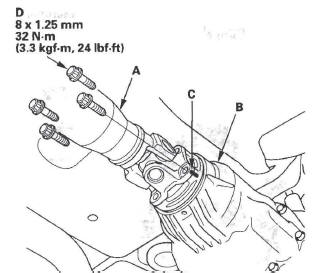
9. Install the No.2 propeller shaft (A) onto the rear differential (B) by aligning the reference marks (C) made during removal. Make sure you use new mounting bolts (D).
10. Fill the rear differential with the differential fluid to the proper level.
READ NEXT:
 Driveline/Axle
Special Tools
Oil Seal Driver
Attachment, 52 x 55 mm
Half Shaft Base
Threaded Adapter, 24 x 1.5 mm
Threaded Adapter, 26 x 1.5 mm
Attachment, 35 mm I.D.
Driver
Inner Handle, 30 mm
Oil Seal
Driveshaft Inspection
1. Check the inboard boot (A) and the outboard boot
(B) on the driveshaft (C) for cracks, damage, leaking
grease, and loose boot bands (D). If any damage is
found, replace the boot and boot bands.
2.
Front Driveshaft Disassembly
Special Tools Required
Threaded adapter, 26 x 1.5 mm 07XAC-001030A
Slide hammer, 5/8"-18 UNF, commercially available
Inboard Joint Side
1. Remove the set ring (A) from the inboard joint.
2. Remov
SEE MORE:
Brake Booster
Brake Booster Test
Functional Test
1. With the engine stopped, press the brake pedal several times to deplete
the vacuum reservoir, then press the brake pedal hard, and hold it for 15
seconds. If the brake pedal sinks, either the master cylinder is bypassing
internally, or the brake system is lea
Rear Bumper
Rear Bumper Removal/Installation
NOTE:
Have an assistant help you when removing and
installing the rear bumper.
Take care not to scratch the rear bumper and body.
Put on gloves to protect your hands.
1. Remove the rear splash guard.
2. Remove the caps (A). Remove the bolts (B, C) and
clips (D
