Honda CR-V: Lower Ball Joint Replacement
Special Tools Required
- Ball joint remover, 32 mm 07MAC-SL0A 102
- Ball joint thread protector, 14 mm 071AF-S3VA000
1. Remove the front wheel.
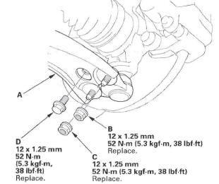
2. Remove the flange bolt and flange nuts from the lower arm (A).
NOTE: During installation, install a new flange bolt and new flange nuts. After lightly tightening all three fasteners, tighten them to the specified torque in the following order; the nut on the front (B), the nut on the rear (C), then the bolt (D).
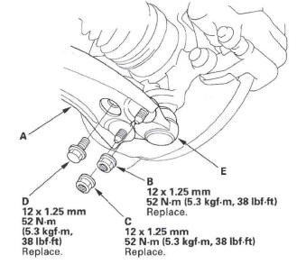
3. Disconnect the lower ball joint (E) from the lower arm.
4. Remove the lock pin (A) from the lower ball joint pin (B) them remove the castle nut (C).
NOTE: During installation, install the lock pin after tightening new castle nut.
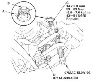
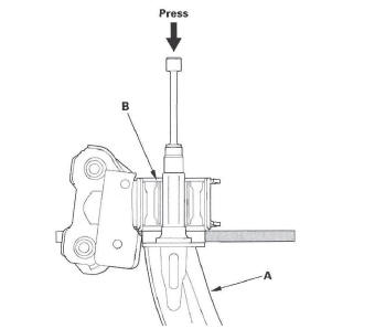
5. Install the ball joint thread protector (D).
6. Disconnect the lower ball joint from the knuckle using the ball joint remover, then remove the lower ball joint.
7. Install the lower ball joint in the reverse order of removal, and note these items:
- First install all the components, and lightly
tighten the bolts and nuts, then tighten the lower
ball joint to the lower arm to the specified torque.
Raise the suspension to load it with the vehicle's weight before fully tightening the lower ball joint to the knuckle to the specified torque values.
- Torque the castle nut to the lower torque specification, then tighten it only far enough to align the slot with the ball joint pin hole. Do not align the castle nut by loosening it.
- Tighten all mounting hardware to the specified torque values.
- Before installing the wheel, clean the mating surface of the brake disc and the inside of the wheel.
- Check the wheel alignment, and adjust it if necessary.
Ball Joint Boot Replacement
Special Tools Required
Attachment, 40 mm 07GAF-SE00200
1. Remove the lower ball joint.
2. Remove the boot.
3. Pack the interior and lip (A) of a new boot with grease. Keep the grease off of the boot-to-lower ball housing mating surfaces (B).
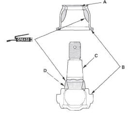
4. Wipe the grease off the tapered portion of the pin (C), and pack fresh grease into the base (D). Do not let dirt or other foreign materials get into the boot.
5. Install the boot on the ball joint, then squeeze it gently to force out any air.
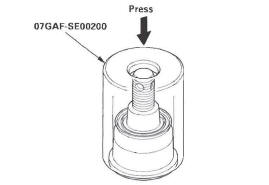
6. Press the boot with the attachment until the bottom seats on the lower ball housing evenly all the way around.
7. After installing a boot, wipe any grease off the exposed portion of the ball joint pin.
8. Install the lower ball joint.
Lower Arm Removal/Installation
Removal/Installation
1. Raise the front of the vehicle, and support it with safety stands in the proper locations.
2. Remove the front wheel.
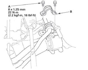
3. Remove the flange bolts (A) and the bushing holder (B).
4. Remove the flange bolt and flange nuts from the lower arm (A).
NOTE: During installation, install a new flange bolt and new flange nuts. After lightly tightening all three fasteners, tighten them to the specified torque in the following order; the nut on the front (B), the nut on the rear (C), then the bolt (D).
5. Disconnect the lower ball joint from the lower arm.
6. Remove the lower arm mounting bolt (A).
NOTE: During installation, install a new mounting bolt.
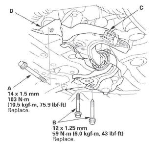
7. Remove the lower arm mounting bolts (B), then remove the lower arm (C) from the front suspension subframe (D).
NOTE: During installation, install new mounting bolts.
8. Install the lower arm in the reverse order of removal, and note these items:
- First install all the components, and lightly tighten the bolts and nuts, then raise the suspension to load it with the vehicle's weight before fully tightening to the specified torque values.
- Tighten all mounting hardware to the specified torque values.
- Before installing the wheel, clean the mating surface of the brake disc and the inside of the wheel.
- Check the wheel alignment, and adjust it if necessary.
Bushing Replacement
1. Press out the lower arm (A) with the suitable socket wrench and a hydraulic press, and remove the lower arm from the bushing (B).
2. Apply mild soap and water to the new bushing surface.
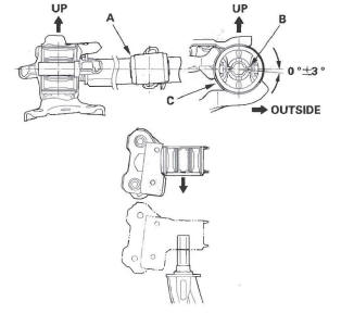
3. Align the angle of the lower arm (A) and the tab portion (B) of the bushing (C). Press in the bushing by hand first.
NOTE:
- The installed bushing's tab portion points upward and downward to the installed lower arm.
- Make sure the up/down direction of the bushing.
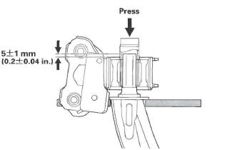
4. Press in the bushing with a suitable socket wrench and a hydraulic press.
5. Adjust the distance between the top of the lower arm and the bushing surface to the dimension shown.
READ NEXT:
 Stabilizer
Stabilizer Link Removal/Installation
1. Raise the front of the vehicle, and support it with safety stands in the
proper locations.
2. Remove the front wheel.
3. Remove the flange nuts while holdi
Damper/Spring
Damper/Spring Removal and Installation
Removal
1. Turn the ignition switch ON (II), then turn on the
windshield wipers. Turn the ignition switch off
when the wipers are near the A-pillars.
2. Raise
SEE MORE:
Door Lock
Door Lock Actuator Test
Driver's Door and Left Rear Door
1. Remove the door panel.
Front
Rear
2. Disconnect the 10P connector (A) from the actuator
(B).
NOTE: The illustration shows the driver's door.
3. Check the actuator operation by connecting power
and ground according to the table. To
Rear Brake
Rear Brake Pad Inspection and Replacement
Special Tools Required
Brake caliper piston compressor 07AAE-SEPA101
CAUTION
Frequent inhalation of brake pad dust, regardless of material
composition, could be hazardous to -your health.
Avoid breathing dust particles.
Never use an air hose or brush to
