Honda CR-V: Intake Air System
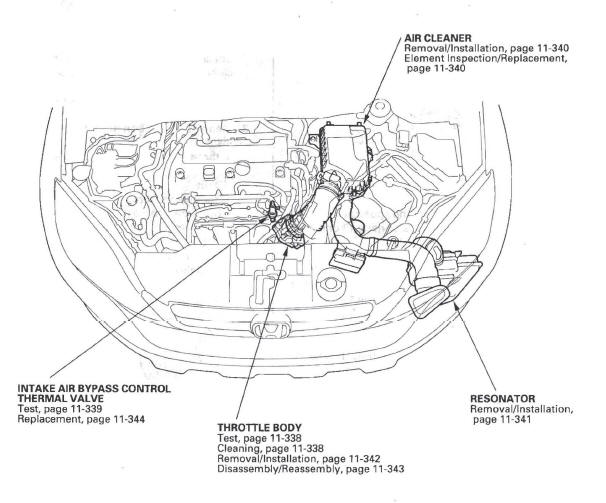
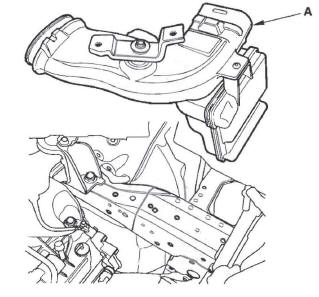
Component Location Index
-
AIR CLEANER
-
RESONATOR
-
THROTTLE BODY
-
INTAKE AIR BYPASS CONTROL THERMAL VALVE
Throttle Body Test
Carbon Accumulation Check
NOTE: If the malfunction indicator lamp (MIL) has been reported on, check for diagnostic trouble codes (DTCs).
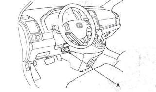
1. Connect the HDS to the data link connector (DLC) (A) located under the driver's side of the dashboard.
2. Start the engine. Hold the engine speed at 3,000 rpm without load (in Park or neutral) until the radiator fan comes on, then let it idle.
3. Check the REL TP SENSOR in the DATA LIST with the HDS. The reading should be below 2.46 deg. If it is not, clean the throttle body.
Throttle Position Learning Check
NOTE: If the malfunction indicator lamp (MIL) has been reported on, check for diagnostic trouble codes (DTCs).
1. Connect the HDS to the data link connector (OLC) (A) located under the driver's side of the dashboard.
2. Select the INSPECTION MENU with the HDS.
3. Do the TP POSITION CHECK in the ETCS TEST. If needed, clean the throttle body.
Throttle Body Cleaning
CAUTION
Do not insert your fingers into the installed throttle body when you turn the ignition switch ON (II) or while the ignition switch is ON (II). If you do, you will seriously injure your fingers if the throttle valve is activated.
1. Check for damage to the air cleaner. If the air cleaner is damaged, replace it.
2. Remove the throttle body.
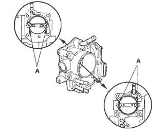
3. Clean off the carbon from the throttle valve and inside the throttle body with a paper towel soaked in throttle plate and induction cleaner.
NOTE:
- Remove the throttle body to clean it.
- Be careful not to pinch your fingers.
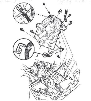
- To avoid removing the molybdenum coating, do not clean the bearing area of the throttle shaft (A).
- Do not spray throttle plate and induction cleaner directly on the throttle body.
- Use Honda genuine throttle plate and induction cleaner.
4. Install the throttle body.
5. Reset the PCM with the HDS.
6. Turn the ignition switch ON (II), and wait for 2 seconds.
7. Do the PCM idle learn procedure.
Intake Air Bypass Control Thermal Valve Test
Special Tools Required
Vacuum pump/gauge, 0-30 in.Hg, Snap-on YA4000A or equivalent, commercially available
1. Remove the intake manifold cover (see step 5). Remove the vacuum hose (A) from the air intake duct, and connect a vacuum pump/gauge, 0-30 in.Hg, to the hose.
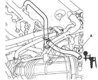
2. Start the engine, and let it idle.
NOTE: Engine coolant temperature must be below 149 F (65 ºC).
3. Raise and lower the engine speed, and make sure the vacuum gauge reading changes as the engine speed changes.
If the vacuum reading does not change, check for these problems:
- Misrouted, leaking, broken, or clogged intake air bypass control system vacuum lines.
- A cracked or damaged intake air bypass control thermal valve. Replace the intake air bypass control thermal valve.
4. Hold the engine speed at 3,000 rpm without load (in Park or neutral) until the radiator fan comes on, then let it idle.
5. Raise and lower the engine speed, and make sure the vacuum gauge reading does not change as the rpm changes.
If the vacuum reading changes, check for these problems:
- Misrouted, leaking, broken, or clogged intake air bypass control system vacuum lines.
- A cracked or damaged intake air bypass control thermal valve. Replace the intake air bypass control thermal valve.
Air Cleaner Removal/Installation
1. Make sure you have the anti-theft code for the audio system.
2. Remove the battery.
3. Remove the bolts (A).
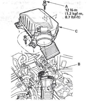
4. Disconnect the MAF sensor/IAT sensor connector (B).
5. Remove the air cleaner (C).
6. Install the parts in the reverse order of removal.
7. Reinstall the battery, and do these items:
- Enter the anti-theft code for the audio system.
- Reset the clock.
Air Cleaner Element Inspection/Replacement
1. Open the air cleaner housing cover (A).
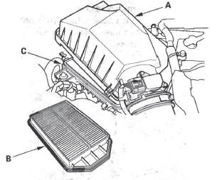
2. Remove the air cleaner element (B) from the air cleaner housing (C).
3. Check the air cleaner element for damage or clogging. If there is damage or clogging, replace the air cleaner element.
NOTE: Do not use compressed air to clean the air cleaner element.
4. Install the parts in the reverse order of removal.
5. If the maintenance minder requires air cleaner replacement, reset the maintenance minder, and this procedure is complete. If the maintenance minder did not require air cleaner replacement, go to step 6.
6. Select BODY ELECTRICAL with the HDS.
7. Select ADJUSTMENT in the GAUGES MENU with the HDS.
8. Select RESET in the MAINTENANCE MINDER with the HDS.
9. Select MAINTENANCE SUB ITEM 2 RESET with the HDS.
10. Reset the PCM with the HDS.
11. Do the PCM idle learn procedure.
Resonator Removal/Installation
1. Make sure you have the anti-theft code for the audio system.
2. Remove the battery.
3. Remove the battery base (A).
4. Remove the air intake duct. (A).
5. Remove the front bumper.
6. Remove the resonator (A) and duct (B).

7. Install the parts in the reverse order of removal.
8. Reinstall the battery, and do these items:
- Enter the anti-theft code for the audio system.
- Reset the clock.
Throttle Body Removal/Installation
CAUTION
Do not insert your fingers into the installed throttle body when you turn the ignition switch ON (II) or while the ignition switch is ON (II). If you do, you will seriously injure your fingers if the throttle valve is activated.
NOTE: If you are replacing or cleaning the throttle body, start at step 1. If you are removing the throttle body, start at step 4.
1. Connect the HDS to the DLC while the engine is stopped.
2. Select the INSPECTION MENU on the HDS.
3. Do the TP POSITION CHECK in the ETCS TEST.
4. Remove the air intake duct (A).
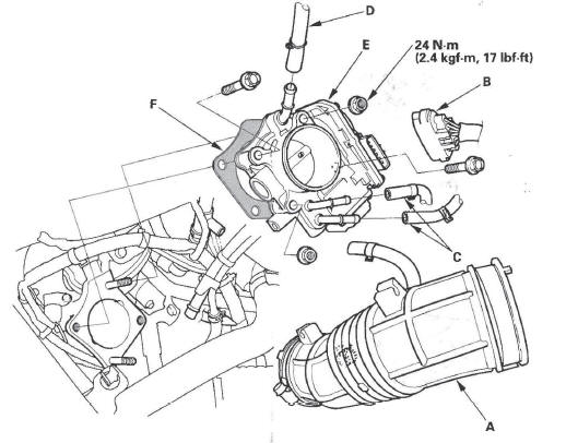
5. Disconnect the throttle body connector (B).
6. Disconnect the water bypass hoses (C), and plug the water bypass hoses.
7. Disconnect the vacuum hose (D).
8. Remove the throttle body (E).
9. Install the parts in the reverse order of removal with a new gasket (F), then check these items:
- Do the PCM idle learn procedure after replacing the throttle body.
- Refill the radiator with engine coolant.
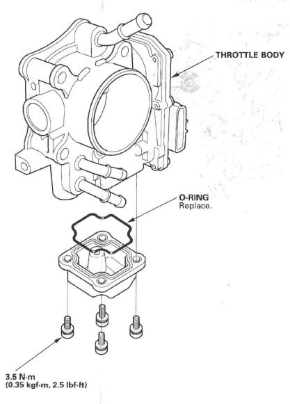
Throttle Body Disassembly/Reassembly
Intake Air Bypass Control Thermal Valve Replacement
1. Remove the intake manifold cover.
2. Remove the air intake duct.
3. Disconnect the hoses (A).
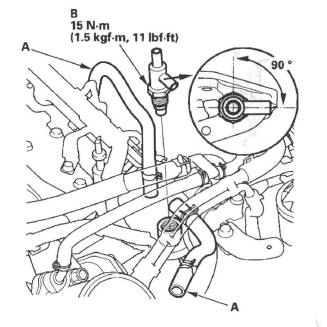
4. Remove the intake air bypass control thermal valve (B).
5. Install the parts in the reverse order of removal.
NOTE: Position the valve as shown.
READ NEXT:
 Catalytic Converter System
Component Location Index
CATALYTIC CONVERTER
Removal/Installation
POWERTRAIN CONTROL MODULE (PCM)
General Troubleshooting information
Replacement
DTC Troubleshooting
EGR System
Component Location Index
EXHAUST GAS RECIRCULATION (EGR) VALVE
POWERTRAIN CONTROL MODULE (PCM)
EXHAUST GAS RECIRCULATION (EGR) PLATE
DTC Troubleshooting
DTC P0401: EGR Insufficient Flow
NOT
PCV System
Component Location Index
PCV VALVE
PCV Valve Inspection
1. Check the PCV valve (A), hoses (B), and
connections for leaks or restrictions.
2. At idle, make sure there is a clicking sound from t
SEE MORE:
Driver’s Seat Power Adjustments
EX-L and Canadian EX models
See pages for important safety
information and warnings about how to
properly position the seats and seatbacks.
The controls for the power
adjustable driver’s seat are on the
outside edge of the seat bottom. You
can adjust the seat with the ignition
switch
Front Driveshaft Reassembly
Exploded View
NOTE: Refer to the Exploded View as needed during
this procedure.
Inboard Joint Side
1. Wrap the splines with vinyl tape (A) to prevent
damaging to the inboard boot.
2. Install the inboard boot onto the drives haft, then
remove the vinyl tape. Be careful not to damage the
inboard boo
