Honda CR-V: Engine Compression Inspection
NOTE: After this inspection, you must reset the powertrain control module (PCM), otherwise the PCM will continue to stop the injectors from functioning.
Select PCM reset using the Honda Diagnostic System (HDS).
1. Warm up the engine to normal operating temperature (cooling fan comes on).
2. Turn the ignition switch OFF.
3. Connect the HDS to the data link connector (DLC) (see step 2).
4. Turn the ignition switch ON (II).
5. Make sure the HDS communicate, with the vehicle and the PCM. If it doesn't communicate, troubleshoot the DLC circuit.
6. Select PGM-FI, INSPECTION, then ALL INJECTORS OFF on the HDS.
7. Remove the four ignition coils.
8. Remove the four spark plugs.
9. Attach the compression gauge to the spark plug hole.
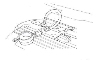
10. Open the throttle fully, then crank the engine with the starter motor and measure the compression.
Compression Pressure: Above 930 kPa (9.5 kgf/cm2, 135 psi)
11. Measure the compression on the remaining cylinders.
Maximum Variation: Within 200 kPa (2.0 kgf/cm2, 28 psi)
12. If the compression is not within specifications, check the following items, then remeasure the compression.
- Damaged or worn valves and seats
- Damaged cylinder head gasket
- Damaged or worn piston rings
- Damaged or worn piston and cylinder bore
13. Select the PCM reset to cancel the ALL INJECTORS OFF function on the HDS.
VTEC Rocker Arm Test
Special Tools Required
- Air pressure regulator 07 AAJ-PNAA 101
- VTEC air adapter 07ZAJ-PNAA101
- VTEC air stopper 07ZAJ-PNAA200
- Air joint adapter 07ZAJ-PNAA300
1. Start the engine, and let it run for 5 minutes, then turn the ignition switch OFF.
2. Remove the cylinder head cover.
3. Set the No.1 piston at top dead center (TDC) (see step 5).
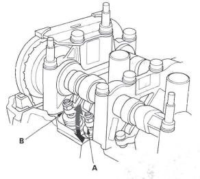
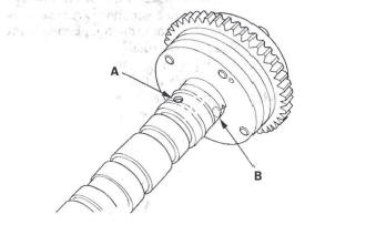
4. Verify that the intake primary rocker arm (A) moves independently of the intake secondary rocker arm (B).
- If the intake primary rocker arm does not move, remove the primary and secondary rocker arms as an assembly and check that the pistons in the secondary and primary rocker arms move smoothly. If any rocker arm needs replacing, replace the primary and secondary rocker arms as an assembly, and test.
- If the intake primary rocker arm moves freely, go to step 5.
5. Repeat step 4 on the remaining intake primary rocker arms with each piston at TDC. When all the primary rocker arms pass the test, go to step 6.
6. Check that the air pressure on the shop air compressor gauge indicates over 400 kPa (4 kgf/cm2, 57 psi).
7. Inspect the valve clearance.
8. Remove the sealing bolt (A) from the relief hole, and install the VTEC air stopper (B).
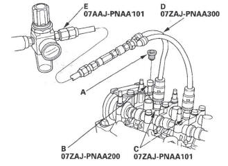
9. Remove the No.2 and No.3 camshaft holder bolts, and install the VTEC air adapters (C) finger-tight.
10. Connect the air joint adapter (D) and air pressure regulator (E).
11. Loosen the valve on the regulator, and apply the specified air pressure.
Specified Air Pressure: 290 kPa (3.0 kgf/cm2, 42 psi)
NOTE: If the synchronizing piston does not move after applying air pressure; move the primary or secondary rocker arm up and down manually by rotating the crankshaft clockwise.
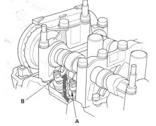
12. With the specified air pressure applied, move the intake primary rocker arm (A) for the No. 1 cylinder.
The primary rocker arm and secondary rocker arm (B) should move together.
If the intake secondary rocker arm does not move, remove the primary and secondary rocker arms as an assembly, and check that the pistons in the primary and secondary rocker arms move smoothly. If any rocker arm needs replacing, replace the primary and secondary rocker arms as an assembly, and test.
VTC Actuator Inspection
1. Remove the cam chain.
2. Loosen the rocker arm adjusting screws (see step 2).
3. Remove the camshaft holder (see step 3).
4. Remove the intake camshaft.
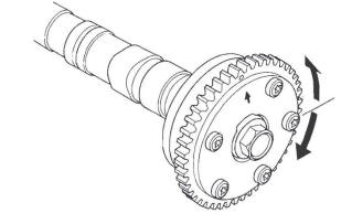
5. Check that the variable valve timing control (VTC) actuator is locked by turning the VTC actuator counterclockwise. If not locked, turn the VTC actuator clockwise until it stops, then recheck it. If it is still not locked, replace the VTC actuator.
6. Seal the advance holes (A) and retard holes (B) in the No.1 camshaft journal with tape.
7. Punch a hole in the tape over one of the advance holes.
8. Apply air to the advance hole to release the lock.
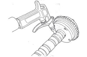
9. Check that the VTC actuator moves smoothly. If the VTC actuator does not move smoothly, replace the VTC actuator.
10. Remove the tape and adhesive residue from the camshaft journal.
11. Make sure the punch marks on the VTC actuator and exhaust camshaft sprocket are facing up, then set the camshafts in the head (see step 6).
12. Set the camshaft holders and chain guide B in place (see step 7).
13. Tighten the camshaft holder bolts to the specified torque (see step 8).
14. Hold the camshaft, and turn the VTC actuator clockwise until you hear it click. Make sure to lock the VTC actuator by turning it.
15. Install the cam chain.
16. Adjust the valve clearance.
READ NEXT:
 Valve Clearance Adjustment
Special Tools Required
Adjuster 07MAA-PR70110
Locknut wrench 07MAA-PR70120
NOTE: Adjust the valves only when the cylinder head
temperature is less than 100 ºF (38 ºC).
1. Remove the cylinder hea
Cam Chain Removal
NOTE: Keep the cam chain away from magnetic fields.
1. Remove the front wheels.
2. Remove the splash shield (see step 21).
3. Remove the drive belt.
4. Remove the cylinder head cover.
5. Set the N
Cam Chain Installation
NOTE:
Keep the cam chain away from magnetic fields.
Before this procedure, check that the variable valve
timing control (VTC) actuator is locked by turning the
VTC actuator counterclockwise. If n
SEE MORE:
Valve, Spring, and Valve Seal Installation
Special Tools Required
Stem seal driver 07PAD-001 0000
Valve spring compressor attachment 07757-PJ1010A
1. Coat the valve stems with engine oil. Install the
valves in the valve guides.
2. Check that the valves move up and down smoothly.
3. Install the spring seats on the cylinder head.
4. Ins
Nothing Happens or the Starter Motor Operates Very Slowly
When you turn the ignition switch to
the START (III) position, you do not
hear the normal noise of the engine
trying to start. You may hear a
clicking sound, a series of clicks, or
nothing at all.
Check these things:
Check the transmission interlock.
The transmission must be in Park
o
