Honda CR-V: Cam Chain Removal
NOTE: Keep the cam chain away from magnetic fields.
1. Remove the front wheels.
2. Remove the splash shield (see step 21).
3. Remove the drive belt.
4. Remove the cylinder head cover.
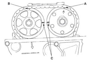
5. Set the No.1 piston at top dead center (TDG). The punch mark (A) on the variable valve timing control (VTG) actuator and the punch mark (B) on the exhaust camshaft sprocket should be at the top.
Align the TDG marks (C) on the VTC actuator and exhaust camshaft sprocket.
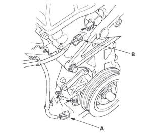
6. Disconnect the crankshaft position (CKP) sensor connector (A) and VTC oil control solenoid valve connector (B).
7. Remove the VTC oil control solenoid valve.
8. Remove the crankshaft pulley.
9. Support the engine with a jack and a wood block under the oil pan.
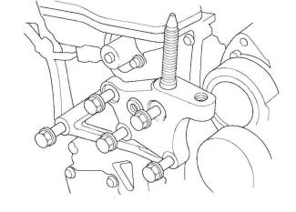
10. Remove the upper torque rod.
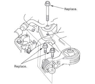
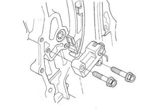
11. Remove the ground cable (A). then remove the side engine mount bracket (B).
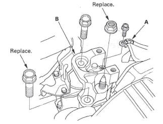
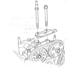
12. Remove the side engine mount bracket mounting bolts.
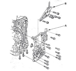
13. Remove the cam chain case (A) and side engine mount bracket (B).
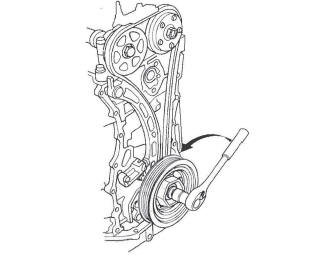
14. Loosely install the crankshaft pulley.
15. Turn the crankshaft counterclockwise to compress the auto-tensioner.
16. Align the holes on the lock (A) and the auto-tensioner (B), then insert a 1.2 mm (0.05 in.) diameter pin or lock pin (P/N 14511-PNA-003) (C) into the holes. Turn the crankshaft clockwise to secure the pin.
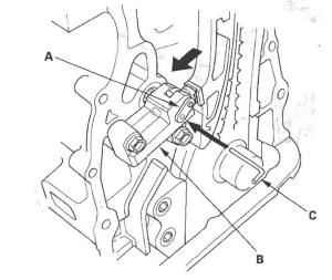
17. Remove the auto-tensioner.
18. Remove cam chain guide B.
19. Remove cam chain guide A and tensioner arm (B).
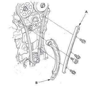
20. Remove the cam chain.
READ NEXT:
 Cam Chain Installation
NOTE:
Keep the cam chain away from magnetic fields.
Before this procedure, check that the variable valve
timing control (VTC) actuator is locked by turning the
VTC actuator counterclockwise. If n
Auto-tensioner Removal and Installation
Removal
1. Remove the chain case cover.
2. Turn the crankshaft counterclockwise to compress
the auto-tensioner.
3. Align the holes on the lock (A) and the auto-tensioner
(B), then insert a 1.2 mm (0
Cam Chain Inspection
1. Remove the front wheels.
2. Remove the splash shield (see step 21).
3. Remove the drive belt.
4. Remove the cylinder head cover.
5. Set the No.1 piston at top dead center (TDC). The
punch mark
SEE MORE:
Cruise Control
Component Location Index
CRUISE MAIN INDICATOR
CRUISE CONTROL INDICATOR
CRUISE CONTROL
COMBINATION SWITCH
BRAKE PEDAL POSITION SWITCH
POWERTRAIN CONTROL MODULE (PCM)
TRANSMISSION RANGE SWITCH
Symptom Troubleshooting
Index
Circuit Diagram
Cruise Control Input Test
1. Connect
Camshaft Inspection
NOTE: Do not rotate the camshaft during inspection.
1. Remove the rocker arm assembly.
2. Put the rocker shaft holders, camshaft, and
camshaft holders on the cylinder head, then tighten
the bolts, in sequence, to the specified torque.
NOTE: If the engine does not have bolt 21, skip it
and continu
