Honda CR-V: Cam Chain Inspection
1. Remove the front wheels.
2. Remove the splash shield (see step 21).
3. Remove the drive belt.
4. Remove the cylinder head cover.
5. Set the No.1 piston at top dead center (TDC). The punch mark on the variable valve timing control (VTC) actuator and the punch mark on the exhaust camshaft sprocket should be at the top. Align the TDC marks on the VTC actuator and exhaust camshaft sprocket (see step 5).
6. Disconnect the crankshaft position (CKP) sensor connector and VTC oil control solenoid valve connector (see step 6).
7. Remove the VTC oil control solenoid valve.
8. Remove the crankshaft pulley.
9. Support the engine with a jack and a wood block under the oil pan.
10. Remove the upper torque rod (see step 10).
11. Remove the ground cable, then remove the side engine mount bracket (see step 11).
12. Remove the side engine mount bracket mounting bolts (see step 12).
13. Remove the cam chain case and side engine mount bracket (see step 13).
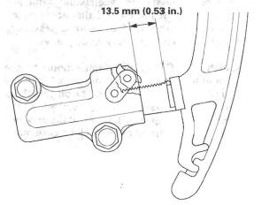
14. Measure the tensioner rod length between the tensioner body and bottom of the flat surface section on the tensioner rod. If the length is more than the service limit, replace the cam chain and the oil pump chain.
Tensioner Rod Length
Service Limit: 13.5 mm (0.53 in.)
15. Check the chain case oil seal for damage. If the oil seal is damaged, replace the chain case oil seal.
16. Remove all of the old liquid gasket from the chain case mating surfaces, bolts, and bolt holes.
17. Clean and dry the chain case mating surfaces.
18. Apply liquid gasket, P/N 08717-0004, 08718-0001, 08718-0003, or 08718-0009, evenly to the engine block mating surface of the chain case. Install the component within 5 minutes of applying the liquid gasket (see step 15).
NOTE:
- If you apply liquid gasket P/N 08718-0012, the component must be installed within 4 minutes.
- If too much time has passed after applying the liquid gasket, remove the old liquid gasket and residue, then reapply new liquid gasket.
19. Apply liquid gasket to the engine block upper surface contact areas on the chain case and lower block upper surface contact areas on the chain case (see step 16).
20. Apply liquid gasket, P/N 08717-0004, 08718-0001, 08718-0003, or 08718-0009, evenly to the oil pan mating surface of the chain case. Install the component within 5 minutes of applying the liquid gasket (see step 17).
NOTE:
- If you apply liquid gasket P/N 08718-0012, the component must be installed within 4 minutes.
- If too much time has passed after applying the liquid gasket, remove the old liquid gasket and residue, then reapply new liquid gasket.
21. Install the new O-ring, side engine mount bracket, and mounting bolts on the chain case. Set the edge of the chain case to the edge of the oil pan, then install the chain case on the engine block (see step 18). Wipe off the excess liquid gasket on the oil pan and chain case mating area.
NOTE:
- When installing the chain case, do not slide the bottom surface onto the oil pan mounting surface.
- Wait at least 30 minutes before filling the engine with oil.
- Do not run the engine for at least 3 hours after installing the chain case.
22. Tighten the side engine mount bracket mounting bolts (see step 19).
23. Install the side engine mount bracket, then loosely tighten the new bolt and nut, and loosely tighten the bolt. Install the ground cable (see step 20).
24. Remove the air cleaner housing assembly.
25. Loosen the transmission mounting bolt and nuts (see step 23).
26. Raise the lift to full height.
27. Loosen the lower torque rod mounting bolt (see step 25).
28. Lower the vehicle on the lift.
29. Tighten the side engine mount mounting bolts and nut (see step 27).
30. Tighten the transmission mounting bolt and nuts (see step 28).
31. Raise the lift to full height.
32. Tighten the lower torque rod mounting bolt (see step 30).
33. Lower the vehicle on the lift.
34. Install the air cleaner housing assembly.
35. Install the upper torque rod, then tighten the new upper torque rod mounting bolts in the numbered sequence shown (see step 33).
36. Install the VTC oil control solenoid valve.
37. Connect the CKP sensor connector and VTC oil control solenoid valve connector (see step 36).
38. Install the crankshaft pulley.
39. Install the cylinder head cover.
40. Install the drive belt.
41. Do the CKP pattern clear/CKP learn procedure.
READ NEXT:
 CKP Pulse Plate Replacement
1. Remove the front wheels.
2. Remove the splash shield (see step 21).
3. Remove the drive belt.
4. Remove the cylinder head cover.
5. Set the No.1 piston at top dead center (TDC). The
punch mark
Cylinder Head Cover Removal/Installation
Cylinder Head Cover Removal
1. Remove the intake manifold cover.
2. Remove the four ignition coils.
3. Disconnect the evaporative emission (EVAP)
canister purge valve connector.
4. Remove the dipst
Cylinder Head Removal
NOTE:
Use fender covers to avoid damaging painted
surfaces.
To avoid damage, unplug the wiring connectors
carefully while holding the connector portion.
To avoid damaging the cylinder head, wait
SEE MORE:
Bluetooth Wireless Technology
The Bluetooth name and logos are
registered trademarks owned by
Bluetooth SIG, Inc. and any use of
such marks by Honda Motor Co.,
Ltd. is under license. Other
trademarks and trade names are
those of their respective owners.
As required by the FCC:
This device complies with Part 15 of t
Relay and Control Unit
Locations
Engine Compartment
VSA MODULATOR-CONTROL UNIT
AUXILIARY UNDER-HOOD
RELAY BOX
POWER MIRROR
DEFOGGER RELAY
PCM
RADIATOR FAN RELAY
ELECTRONIC THROTTLE CONTROL SYSTEM (ETCS) CONTROL RELAY
ELD UNIT
PGM-FI MAIN RELAY 1 (FI MAIN)
UNDER-HOOD FUSE/RELAY BOX
FAN CONTROL RELAY
BLOWER MOTOR RELAY
