Honda CR-V: DTC P0705: Short in Transmission Range Switch Circuit (Multiple Shift-Position Input)
NOTE:
- Before you troubleshoot, record all freeze data and any on-board snapshot, and review General Troubleshooting Information.
- This code is caused by an electrical circuit problem and cannot be caused by a mechanical problem in the transmission.
1. Clear the DTC with the HDS.
2. Start the engine.
3. With the brake pedal pressed, move the shift lever through all positions. Stop for at least 1 second in each position, and monitor the OBD STATUS for P0705 in the DTCs/Freeze Data in A/T Mode Menu for a pass/fail.
Does the HDS indicate FAILED? YES-Go to step 4.
NO-Intermittent failure, the system is OK at this time. Check for an intermittent short in the wire between the transmission range switch and the PCM. If the HDS indicates NOT COMPLETED, return to step 2 and recheck.
4. Turn the ignition switch OFF.
5. Inspect the transmission range switch.
Is the switch OK? YES-With the switch connector disconnected, go to step 6.
NO-Replace the transmission range switch, then go to step 53.
6. Turn the ignition switch ON (II).
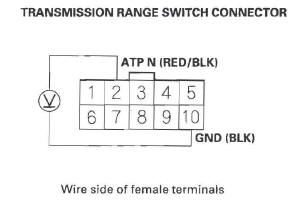
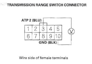
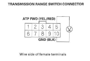
7. Measure the voltage between transmission range switch connector terminals No.6 and No. 10.
Is there battery voltage? YES-Go to step 13.
NO-Go to step 8.
8. Turn the ignition switch OFF.
9. Jump the SCS line with the HDS.
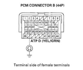
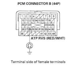
10. Disconnect PCM connector B (44P).
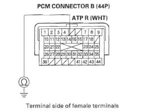
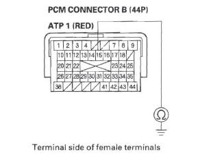
11. Check for continuity between PCM connector terminal B13 and body ground.
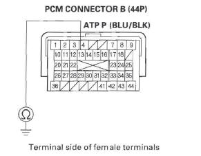
Is there continuity? YES-Repair short in the wire between PCM connector terminal B13 and the transmission range switch, then go to step 53.
NO-Go to step 12.
12. Check for continuity between transmission range switch connector terminal No. 10 and body ground.
Is there continuity? YES-Go to step 48.
NO-Repair open in the wire between transmission range switch connector terminal No. 10 and ground (G 101), or repair poor ground (G 101), then go to step 53.
13. Measure the voltage between transmission range switch connector terminals No. 7 and No. 10.
Is there battery voltage? YES-Go to step 18.
NO-Go to step 14.
14. Turn the ignition switch OFF.
15. Jump the SCS line with the HDS.
16. Disconnect PCM connector B (44P).
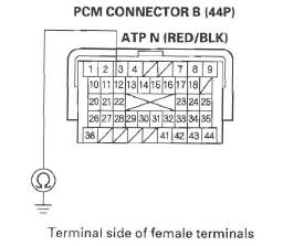
17. Check for continuity between PCM connector terminal B14 and body ground.
Is there continuity? YES-Repair short in the wire between PCM connector terminal B14 and the transmission range switch, then go to step 53.
NO-Go to step 48.
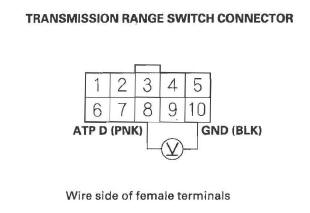
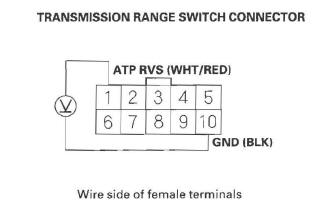
18. Measure the voltage between transmission range switch connector terminals No.2 and No. 10.
Is there about 5 V? YES-Go to step 23.
NO-Go to step 19.
19. Turn the ignition switch OFF.
20. Jump the SCS line with the HDS.
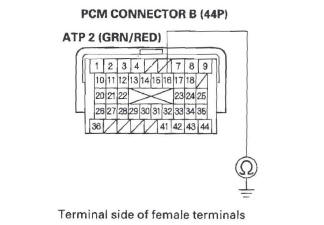
21. Disconnect PCM connector B (44P).
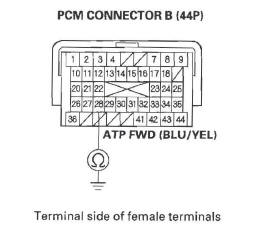
22. Check for continuity between PCM connector terminal B12 and body ground.
Is there continuity? YES-Repair short in the wire between PCM connector terminal B12 and the transmission range switch, then go to step 53.
NO-Go to step 48.
23. Measure the voltage between transmission range switch connector terminals No.8 and No. 10.
Is there battery voltage? YES-Go to step 28.
NO-Go to step 24.
24. Turn the ignition switch OFF.
25. Jump the SCS line with the HDS.
26. Disconnect PCM connector B (44P).
27. Check for continuity between PCM connector terminal B21 and body ground.
Is there continuity? YES-Repair short in the wire between PCM connector terminal B21 and the transmission range switch, then go to step 53.
NO-Go to step 48.
28. Measure the voltage between transmission range switch connector terminals No.3 and No. 10.
Is there battery voltage? YES-Go to step 33.
NO-Go to step 29.
29. Turn the ignition switch OFF.
30. Jump the SCS line with the HDS.
31. Disconnect PCM connector B (44P).
32. Check for continuity between PCM connector terminal B16 and body ground.
Is there continuity? YES-Repair short in the wire between PCM connector terminal B16 and the transmission range switch, then go to step 53.
NO-Go to step 48.
33. Measure the voltage between transmission range switch connector terminals No.9 and No. 10.
Is there battery voltage? YES-Go to step 38.
NO-Go to step 34.
34. Turn the ignition switch OFF.
35. Jump the SCS line with the HDS.
36. Disconnect PCM connector B (44P).
37. Check for continuity between PCM connector terminal B15 and body ground.
Is there continuity? YES-Repair short in the wire between PCM connector terminal B15 and the transmission range switch, then go to step 53.
NO-Go to step 48.
38. Measure the voltage between transmission range switch connector terminals No.5 and No.10.
Is there battery voltage? YES-Go to step 43.
NO-Go to step 39.
39. Turn the ignition switch OFF.
40. Jump the SCS line with the HDS.
41. Disconnect PCM connector B (44P).
42. Check for continuity between PCM connector terminal B28 and body ground.
Is there continuity? YES-Repair short in the wire between PCM connector terminal B28 and the transmission range switch, then go to step 53.
NO-Go to step 48.
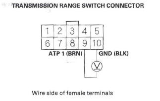
43. Measure the voltage between transmission range switch connector terminals No.1 and No. 10.
Is there battery voltage? YES-Go to step 48.
NO-Go to step 44.
44. Turn the ignition switch OFF.
45. Jump the SCS line with the HDS.
46. Disconnect PCM connector B (44P).
47. Check for continuity between PCM connector terminal B22 and body ground.
Is there continuity? YES-Repair short in the wire between PCM connector terminal B22 and the transmission range switch, then go to step 53.
NO-Go to step 48.
48. Update the A/T software in the PCM if it does not have the latest software, or substitute a known-good PCM.
49. Start the engine.
50. With the brake pedal pressed, move the shift lever through all position. Stop for at least 1 second in each position.
51. Check for DTC(s) in the DTCs/Freeze Data in A/T Mode Menu with the HDS.
Is DTC P0705 indicated? YES-Check for poor connections and loose terminals at the transmission range switch and the PCM. If the PCM was updated, substitute a known-good PCM, then recheck. If the PCM was substituted, go to step 1.
NO-Go to step 52.
52. Monitor the OBD STATUS for P0705 in the DTCs/ Freeze Data in A/T Mode Menu for a pass/fail.
Does the HDS indicate PASSED? YES-If the PCM was updated, troubleshooting is complete. If the PCM was substituted, replace the original PCM. If any other DTCs were indicated on step 51 , go to the indicated DTC's troubleshooting.
NO-If the HDS indicates FAILED, check for poor connections and loose terminals at the transmission range switch and the PCM. If the PCM was updated, substitute a known-good PCM, then recheck. If the PCM was substituted, go to step 1. If the HDS indicates NOT COMPLETED, keep idling until a result comes on.
53. Clear the DTC with the HDS.
54. Start the engine.
55. With the brake pedal pressed, move the shift lever through all position. Stop for at least 1 second in each position.
56. Check for DTC(s) in the DTCs/Freeze Data in A/T Mode Menu with the HDS.
Is DTC P0705 indicated? YES-Replace the transmission range switch, then return to step 53 and recheck.
NO-Go to step 57.
57. Monitor the OBD STATUS for P0705 in the DTCs/ Freeze Data in A/T Mode Menu for a pass/fail.
Does the HDS indicate PASSED? YES-Troubleshooting is complete. If any other DTCs were indicated on step 56, go to the indicated DTC's troubleshooting.
NO-If the HDS indicates FAILED, check for poor connections and loose terminals at the transmission range switch and the PCM, then go to step 1. If the HDS indicates NOT COMPLETED, return to the step 54 and recheck.
READ NEXT:
 DTC P0706: Open in Transmission Range
Switch Circuit
DTC P0706: Open in Transmission Range
Switch Circuit
NOTE:
Before you troubleshoot, record all freeze data and any on-board
snapshot, and review General Troubleshooting Information.
This code is caused by an electrical circuit problem
and cannot b
DTC P0712: Short in ATF Temperature Sensor
Circuit
NOTE:
Before you troubleshoot, record all freeze data and any on-board
snapshot, and review General Troubleshooting Information.
This code is caused by an electrical circuit problem
and cannot b
DTC P0716: Problem in Input Shaft
(Mainshaft) Speed Sensor Circuit
DTC P0716: Problem in Input Shaft
(Mainshaft) Speed Sensor Circuit
DTC P0717: Problem in Input Shaft
(Mainshaft) Speed Sensor Circuit (No Signal
Input)
NOTE:
Before you troubleshoot, record all free
SEE MORE:
Seat Belt Maintenance
For safety, you should check the
condition of your seat belts regularly.
Pull each belt out fully, and look for
frays, cuts, burns, and wear. Check
that the latches work smoothly and
the belts retract easily. If a belt does
not retract easily, cleaning the belt
may correct the problem.
Front Bumper
Front Bumper Removal/Installation
NOTE:
Have an assistant help you when removing and
installing the front bumper.
Take care not to scratch the front bumper and body.
Put on gloves to protect your hands.
1. Remove the front bulkhead cover.
2. Remove the bolts (A) and clips (B, C) securing the
