Honda CR-V: DTC P0706: Open in Transmission Range Switch Circuit
NOTE:
- Before you troubleshoot, record all freeze data and any on-board snapshot, and review General Troubleshooting Information.
- This code is caused by an electrical circuit problem and cannot be caused by a mechanical problem in the transmission.
1. Clear the DTC with the HDS.
2. 4WD model: Raise the vehicle on a lift, make sure it is securely supported, and allow all four wheels to rotate freely.
2WD model: Raise the front of the vehicle, make sure it is securely supported, and allow the front wheels to rotate freely. Or raise the vehicle.
3. Start the engine, and turn the VSA off (the light on the VSA OFF switch comes on). Run the engine in the D position until the vehicle speed reaches 35 mph (56 km/h), then slow down and stop the wheels.
4. Monitor the OBD STATUS for P0706 in the DTCs/ Freeze Data in A/T Mode Menu for a pass/fail.
Does the HDS indicate FAILED? YES-Go to step 5.
NO-Intermittent failure, the system is OK at this time. Check for poor connections or loose terminals at the transmission range switch and the PCM. If the HDS indicates NOT COMPLETED, return to step 3 and recheck.
5. Turn the ignition switch OFF.
6. Inspect the transmission range switch.
Is the switch OK? YES-Go to step 7.
NO-Replace the transmission range switch, then go to step 31.
7. Make sure the transmission range switch is installed correctly, and adjust the shift cable.
8. Clear the DTC with the HDS.
9. Start the engine, and turn the VSA off (the light on the VSA OFF switch comes on). Run the engine in the D position until the vehicle speed reaches 35 mph (56 km/h), then slow down and stop the wheels.
10. Monitor the OBD STATUS for P0706 in the DTCs/ Freeze Data in A/T Mode Menu for a pass/fail.
Does the HDS indicate FAILED? YES-Go to step 11.
NO-Intermittent failure, the system is OK at this time. Check for poor connections or loose terminals at the transmission range switch and the PCM. If the HDS indicates NOT COMPLETED, return to step 9 and recheck.
11. Shift to the D position, and verify the ATP FWD and ATP D inputs with the HDS in the A/T data list.
Is ATP FWD and ATP 0 ON? YES-Go to step 12.
NO-Go to step 17.
12. Shift to the 2 position, and verify the ATF FWD and ATP 2 inputs with the HDS in the A/T data list.
Is ATP FWD and ATP 2 ON? YES-Go to step 13.
NO-Go to step 17.
13. Shift to the 1 position, and verify the ATF FWD and ATP 1 inputs with the HDS in the A/T data list.
Is ATP FWD and ATP 1 ON? YES-Go to step 14.
NO-Go to step 17.
14. Clear the DTC with the HDS.
15. Start the engine, and turn the VSA off (the light on the VSA OFF switch comes on). Run the engine in the D position until the vehicle speed reaches 35 mph (56 km/h), then slow down and stop the wheels.
16. Monitor the OBD STATUS for P0706 in the DTCs/ Freeze Data in A/T Mode Menu for a pass/fail.
Does the HDS indicate FAILED? YES-Go to step 17.
NO-Intermittent failure, the system is OK at this time. Check for poor connections or loose terminals at the transmission range switch and the PCM. If the HDS indicates NOT COMPLETED, return to step 15 and recheck.
17. Turn the ignition switch OFF.
18. Disconnect the transmission range switch connector.
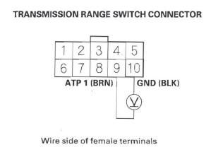
19. Check for continuity between transmission range switch connector terminal No. 1 0 and body ground.
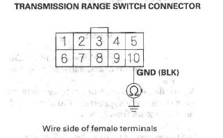
Is there continuity? YES-Go to step 20.
NO-Repair open in the wire between the, transmission range switch and ground (Gl0l), or repair poor ground (Gl01), then go to step 31.
20. Turn the ignition switch ON (II).
21. Measure the voltage between transmission range switch connector terminals No.5 and No. 10.
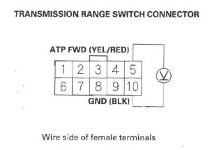
Is there voltage? YES-Go to step 22.
NO-Repair open in the wire between the transmission range switch and PCM connector terminal B28, then go to step 31.
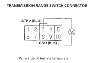
22. Measure the voltage between transmission range switch connector terminals No. 8 and No. 10.
Is there voltage? YES-Go to step 23.
NO-Repair open in the wire between the transmission range switch and PCM connector terminal B21, then go to step 31.
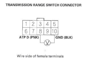
23. Measure the voltage between transmission range switch connector terminals No.3 and No. 10.
Is there voltage? YES-Go to step 24.
NO-Repair open in the wire between the transmission range switch and PCM connector terminal B16, then go to step 31.
24. Measure the voltage between transmission range switch connector terminals No.9 and No. 10.
Is there voltage? YES-Go to step 25.
NO-Repair open in the wire between the transmission range switch and PCM connector terminal B15, then go to step 31.
25. Update the A/T software in the PCM if it does not have the latest software, or substitute a known-good PCM.
26. Turn the ignition switch OFF.
27. 4WD model: Raise the vehicle on a lift, make sure it is securely supported, and allow all four wheels to rotate freely.
2WD model: Raise the front of the vehicle, make sure it is securely supported, and allow the front wheels to rotate freely. Or raise the vehicle.
28. Start the engine, and turn the VSA off (the light on the VSA OFF switch comes on). Run the engine in the D position until the vehicle speed reaches 35 mph (56 km/h), then slow down and stop the wheels.
29. Check for DTC(s) in the DTCs/Freeze Data in A/T Mode Menu with the HDS.
Is DTC P0706 indicated? YES-Check for poor connections and loose terminals at the transmission range switch and the PCM. If the PCM was updated, substitute a known-good PCM, then recheck. lfthe PCM was substituted, go to step 1.
NO-Go to step 30.
30. Monitor the OBD STATUS for P0706 in the DTCs/ Freeze Data in A/T Mode Menu for a pass/fail.
Does the HDS indicate PASSED? YES-If the PCM was updated, troubleshooting is complete. If the PCM was substituted, replace the original PCM. If any other DTCs were indicated on step 29, go to the indicated DTC's troubleshooting.
NO-If the HDS indicates FAILED, check for poor connections and loose terminals at the transmission range switch and the PCM. If the PCM was updated, substitute a known-good PCM, then recheck. If the PCM was substituted, go to step 1. If the HDS indicates NOT COMPLETED, keep idling until a result comes on.
31. Clear the DTC with the HDS.
32. Turn the ignition switch OFF.
33. 4WD model: Raise the vehicle on a lift, make sure it is securely supported, and allow all four wheels to rotate freely.
2WD model: Raise the front of the vehicle, make sure it is securely supported, and allow the front wheels to rotate freely. Or raise the vehicle.
34. Start the engine, and turn the VSA off (the light on the VSA OFF switch comes on). Run the engine in the D position until the vehicle speed reaches 35 mph (56 km/h), then slow down and stop the wheels.
35. Check for DTC(s) in the DTCs/Freeze Data in A/T Mode Menu with the HDS.
Is DTC P0706 indicated? YES-Check for poor connections and loose terminals at the transmission range switch and the PCM, then go to step 1.
NO-Go to step 36.
36. Monitor the OBD STATUS for P0706 in the DTCs/ Freeze Data in A/T Mode Menu for a pass/fail.
Does the HDS indicate PASSED? YES-Troubleshooting is complete. If any other DTCs were indicated on step 35, go to the indicated DTC's troubleshooting.
NO-If the HDS indicates FAILED, check for poor connections and loose terminals at the transmission range switch and the PCM, then go to step 1. If the HDS indicates NOT COMPLETED, return to step 34 and recheck.
DTC P0711: Problem in ATF Temperature Sensor Circuit
NOTE:
- Before you troubleshoot, record all freeze data and any on-board snapshot, and review General Troubleshooting Information.
- This code is caused by an electrical circuit problem and cannot be caused by a mechanical problem in the transmission.
1. Check the ATF temperature with the HDS in the A/T data list.
Does the ATF temperature exceed the ambient-air temperature? YES-Record the ATF temperature. Leave the engine off for more than 30 minutes, and go to step 2.
NO-Record the ATF temperature. Test the stall speed RPM three times. Go to step 2 after stall speed testing.
2. Check the ATF temperature with the HDS.
Does the ATF temperature change? YES-Leave the engine off for more than 30 minutes, and go to step 3.
NO-Replace the ATF temperature sensor, then go to step 5.
3. Check the ECT SENSOR with the HDS.
Is the ECT SENSOR equal to the ambient-air temperature? YES-Go to step 4.
NO-Leave the engine off until the ECT SENSOR reads the same as ambient-air temperature, then go to step 4.
4. Check the ATF TEMP SENSOR with the HDS.
Does the AT F temperature read about the same as the ECT SENSOR? YES-Intermittent failure, the system is OK at this time. Check for poor connections or loose terminals at the ATF temperature sensor and the PCM.
NO-Replace the ATF temperature sensor; then go to step 5.
5. Clear the DTC with the HDS.
6. Test-drive the vehicle for several minutes in the D position through all five gears.
7. Check for DTC(s) in the DTCs/Freeze Data in A/T Mode Menu with the HDS.
Is DTC P0711 indicated? YES-Check for poor connections and loose terminals at the ATF temperature sensor and the PCM, then go to step 1.
NO-Go to step 8.
8. Monitor the OBD STATUS for P0711 in the DTCs/ Freeze Data in A/T Mode Menu for a pass/fail.
Does the HDS indicate PASSED? YES-Troubleshooting is complete. If any other DTCs were indicated on step 7, go to the indicated DTC's troubleshooting.
NO-If the HDS indicates FAILED, check for poor connections and loose terminals at the ATF temperature sensor and the PCM, then go to step 1.
If the HDS indicates NOT COMPLETED, return to step 6 and recheck.
READ NEXT:
 DTC P0712: Short in ATF Temperature Sensor
Circuit
DTC P0712: Short in ATF Temperature Sensor
Circuit
NOTE:
Before you troubleshoot, record all freeze data and any on-board
snapshot, and review General Troubleshooting Information.
This code is caused by an electrical circuit problem
and cannot b
DTC P0716: Problem in Input Shaft
(Mainshaft) Speed Sensor Circuit
DTC P0716: Problem in Input Shaft
(Mainshaft) Speed Sensor Circuit
DTC P0717: Problem in Input Shaft
(Mainshaft) Speed Sensor Circuit (No Signal
Input)
NOTE:
Before you troubleshoot, record all free
DTC P0721: Problem in Output Shaft
(Countershaft) Speed Sensor Circuit
DTC P0721: Problem in Output Shaft
(Countershaft) Speed Sensor Circuit
DTC P0722: Problem in Output Shaft
(Countershaft) Speed Sensor Circuit (No
Signal Input)
NOTE:
Before you troubleshoot, record
SEE MORE:
System Description
Overview
The navigation system is a highly sophisticated, hybrid locating system.
The navigation unit uses global positioning system (GPS) satellite signals,
internal yaw and vehicle speed inputs, and
a map database to show you where you are and to help guide you to a desired
destination.
The na
Important Safety Precautions
To eliminate potential hazards, read
the instructions before you begin,
and make sure you have the tools
and skills required.
Make sure your vehicle is parked
on level ground, the parking brake
is set, and the engine is off.
To clean parts, use a commercially
available degreaser or par
