Honda CR-V: DTC P0116: ECT Sensor 1 Range/Performance Problem
NOTE: Before you troubleshoot, record all freeze data and any on-board snapshot, and review the general troubleshooting information.
1. Turn the ignition switch ON (II).
2. Check ECT SENSOR 1 in the DATA LIST with the HDS.
Is about 176 ºF (80 ºC) or more, or 0.78 V or less indicated? YES-Go to step 6.
NO-Go to step 3.
3. Note the value of ECT SENSOR 1 in the DATA LIST with the HDS.
4. Start the engine. Hold the engine speed at 3,000 rpm without load (in Park or neutral) until the radiator fan comes on, then let it idle.
5. Check ECT SENSOR 1 in the DATA LIST with the HDS.
Does ECT SENSOR 1 change 18 ºF (10 ºC) or more? YES-Intermittent failure, the system is OK at this time. Check for poor connections or loose terminals at ECT sensor 1 and the PCM.
NO-Go to step 11.
6. Note the value of ECT SENSOR 1 in the DATA LIST with the HDS.
7. Turn the ignition switch OFF.
8. Open the hood, and let the engine cool for 3 hours.
9. Turn the ignition switch ON (II).
10. Check ECT SENSOR 1 in the DATA LIST with the HDS.
Does ECT SENSOR 1 change 18 ºF (10 ºC) or more? YES-Intermittent failure, the system is OK at this time. Check for poor connections or loose terminals at ECT sensor 1 and the PCM.
NO-Go to step 11.
11. Turn the ignition switch OFF.
12. Replace ECT sensor 1.
13. Turn the ignition switch ON (II).
14. Reset the PCM with the HDS.
15. Do the PCM idle learn procedure.
16. Check for Temporary DTCs or DTCs with the HDS.
Is DTC P0116 indicated? YES-Check for poor connections or loose terminals at ECT sensor 1 and the PCM, then go to step 1.
NO-Troubleshooting is complete. If any other Temporary DTCs or DTCs are indicated, go to the indicated DTC's troubleshooting.
DTC P0117: ECT Sensor 1 Circuit Low Voltage
NOTE: Before you troubleshoot, record all freeze data and any on-board snapshot, and review the general troubleshooting information.
1. Turn the ignition switch ON (II).
2. Check ECT SENSOR 1 in the DATA LIST with the HDS.
Is about 356 ºF (180 ºC) or more, or 0.08 V or less indicated? YES-Go to step 3.
NO-Intermittent failure, the system is OK at this time. Check for poor connections or loose terminals at ECT sensor 1 and the PCM.
3. Turn the ignition switch OFF.
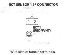
4. Disconnect the ECT sensor 1 2P connector.
5. Turn the ignition switch ON (II).
6. Check ECT SENSOR 1 in the DATA LIST with the HDS.
Is about 356 ºF (180 ºC) or more, or 0.08 V or less indicated? YES-Go to step 7.
NO-Go to step 11.
7. Turn the ignition switch OFF.
8. Jump the SCS line with the HDS.
9. Disconnect PCM connector B (44P).
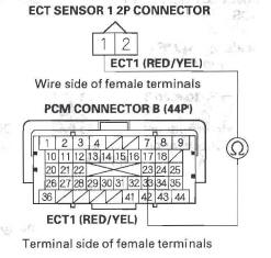
10. Check for continuity between ECT sensor 1 2P connector terminal No. 1 and body ground.
Is there continuity? YES-Repair short in the wire between ECT sensor 1 and the PCM (B23), then go to step 13.
NO-Go to step 18.
11. Turn the ignition switch OFF.
12. Replace ECT sensor 1.
13. Reconnect all connectors.
14. Turn the ignition switch ON (II).
15. Reset the PCM with the HDS.
16. Do the PCM idle learn procedure.
17. Check for Temporary DTCs or DTCs with the HDS.
Is DTC POl17 indicated? YES-Check for poor connections or loose terminals at ECT sensor 1 and the PCM, then go to step 1.
NO-Troubleshooting is complete. If any other Temporary DTCs or DTCs are indicated, go to the indicated DTC's troubleshooting.
18. Reconnect all connectors.
19. Update the PCM if it does not have the latest software, or substitute a known-good PCM.
20. Check for Temporary DTCs or DTCs with the HDS.
Is DTC POl17 indicated? YES-Check for poor connections or loose terminals at ECT sensor 1 and the PCM. If the PCM was updated, substitute a known-good PCM, then recheck. If the PCM was substituted, go to step 1.
NO-If the PCM was updated, troubleshooting is complete. If the PCM was substituted, replace the original PCM. If any other Temporary DTCs or DTCs are indicated, go to the indicated DTC's troubleshooting.
DTC P0118: ECT Sensor 1 Circuit High Voltage
NOTE: Before you troubleshoot, record all freeze data and any on-board snapshot, and review the general troubleshooting information.
1. Turn the ignition switch ON (II).
2. Check ECT SENSOR 1 in the DATA LIST with the HDS.
Is about -40 ºF (-40ºC) or less, or 4.90 V or higher indicated? YES-Go to step 3.
NO-Intermittent failure, the system is OK at this time. Check for poor connections or loose terminals at ECT sensor 1 and the PCM.
3. Turn the ignition switch OFF.
4. Disconnect the ECT sensor 1 2P connector.
5. Connect ECT sensor 1 2P connector terminals No.1 and No.2 with a jumper wire.
6. Turn the ignition switch ON (II).
7. Check ECT SENSOR 1 in the DATA LIST with the HDS.
Is about -40 ºF ( - 40 ºC) or less, or 4.90 V or higher indicated? YES - Go to step 8.
NO-Go to step 20 8. Turn the ignition switch OFF.
9. Remove the jumper wire from the ECT sensor 1 2P connector.
10. Turn the ignition switch ON (II).
11. Measure voltage between ECT sensor 1 2P connector terminal No. 1 and body ground.
Is there about 5 V? YES-Go to step 12.
NO-Go to step 16.
12. Turn the ignition switch OFF.
13. Jump the SCS line with the HDS.
14. Disconnect PCM connector B (44P).
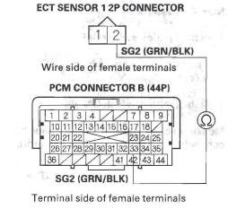
15. Check for continuity between ECT sensor 1 2P connector terminal No.2 and PCM connector terminal B33.
Is there continuity? YES-Go to step 27.
NO-Repair open in the wire between the PCM (B33) and ECT sensor 1, then go to step 22.
16. Turn the ignition switch OFF.
17. Jump the SCS line with the HDS.
18. Disconnect PCM connector B (44P).
19. Check for continuity between ECT sensor 1 2P connector terminal No.1 and PCM connector terminal B23.
Is there continuity? YES-Go to step 27.
NO-Repair open in the wire between the PCM (B23) and ECT sensor 1, then go to step 22.
20. Turn the ignition switch OFF.
21. Replace ECT sensor 1.
22. Reconnect all connectors.
23. Turn the ignition switch ON (II).
24. Reset the PCM with the HDS.
25. Do the PCM idle learn procedure.
26. Check for Temporary DTCs or DTCs with the HDS.
Is DTC PO118 indicated? YES-Check for poor connections or loose terminals at ECT sensor 1 and the PCM, then go to step 1.
NO-Troubleshooting is complete. If any other Temporary DTCs or DTCs are indicated, go to the indicated DTC's troubleshooting.
27. Reconnect all connectors.
28. Update the PCM if it does not have the latest software, or substitute a known-good PCM.
29. Check for Temporary DTCs or DTCs with the HDS.
Is DTC PO118 indicated? YES-Check for poor connections or loose terminals at ECT sensor 1 and the PCM. If the PCM was updated, substitute a known-good PCM, then recheck. If the PCM was substituted, go to step 1.
NO-If the PCM was updated, troubleshooting is complete. If the PCM was substituted, replace the original PCM. If any other Temporary DTCs or DTCs are indicated, go to the indicated DTC's troubleshooting.
DTC P0125: ECT Sensor 1 Malfunction/Slow Response
NOTE: Before you troubleshoot, record all freeze data and any on-board snapshot, and review the general troubleshooting information.
1. Start the engine, and let it idle for 5 minutes or more.
2. Check ECT SENSOR 1 in the DATA LIST with the HDS.
Is about 10 ºF (-12 ºC) or less, or 4.45 V or more indicated? YES-Go to step 9.
NO-Go to step 3.
3. Allow the engine to cool to 104 ºF (40 ºC) or less.
4. Note the value of ECT SENSOR 1 and ECT SENSOR 2 in the DATA LIST with the HDS.
5. Start the engine, and let it idle.
6. Let the engine idle until ECT SENSOR 1 goes up 49 ºF (27 ºC) or more from the recorded temperature.
7. Note the value of ECT SENSOR 2 in the DATA LIST with the HDS.
8. Compare ECT SENSOR 2 and the recorded temperature.
Did ECT SENSOR 2 change 17 F (9.5 ºC) or more? YES-Intermittent failure, the system is OK at this time. Check for poor connections or loose terminals at ECT sensor 1, ECT sensor 2, and the PCM.
NO-Check the thermostat. If the thermostat is OK, go to step 9. If the thermostat is faulty, replace it, then go to step 11.
9. Turn the ignition switch OFF.
10. Replace ECT sensor 1.
11. Turn the ignition switch ON (II).
12. Reset the PCM with the HDS.
13. Do the PCM idle learn procedure.
14. Allow the engine to cool to ambient temperature.
15. Start the engine, and let it idle for 20 minutes.
16. Check for Temporary DTCs or DTCs with the HDS.
Is DTC P0125 indicated? YES-Check for poor connections or loose terminals at the ECT sensor 2 and the PCM, then go to step 1.
NO-Go to step 17.
17. Monitor the OBD STATUS for DTC P0125 in the DTCs MENU with the HDS.
Does the screen indicate PASSED? YES-Troubleshooting is complete. If any other Temporary DTCs or DTCs were indicated in step 16, go to the indicated DTC's troubleshooting.
NO-If the screen indicates FAILED, check for poor connections or loose terminals at the ECT sensor 2 and the PCM, then go to step 1. If the screen indicates NOT COMPLETED, go to step 14.
READ NEXT:
 DTC P0128: Cooling System Malfunction
NOTE: Before you troubleshoot, record all freeze data
and any on-board snapshot, and review the general
troubleshooting information.
1. Turn the ignition switch ON (II).
2. Clear the DTC with the HDS
DTC P0137: Secondary HO2S (Sensor 2)
Circuit Low Voltage
NOTE: Before you troubleshoot, record all freeze data
and any on-board snapshot, and review the general
troubleshooting information.
1. Turn the ignition switch ON (II).
2. Clear the DTC with the HDS
DTC P0300: Random Misfire and Any Combination of the Following
DTC P0301: No.1 Cylinder Misfire Detected
DTC P0302: No.2 Cylinder Misfire Detected
DTC P0303: No.3 Cylinder Misfire Detected
DTC P0304: No.4 Cylinder Misfire Detected
Special Tools Required
Pressur
SEE MORE:
Load Limits
Total Trailer Weight: The
maximum allowable weight of the
trailer and everything in or on it
must not exceed 1,500 lbs (680 kg).
Towing a load that is too heavy can
seriously affect your vehicle’s
handling and performance. It can
also damage the engine and
drivetrain.
Tongue Lo
Remote Audio Controls
If equipped
Three controls for the audio system
are mounted in the steering wheel
hub. These let you control basic
functions without removing your
hand from the wheel.
The VOL button adjusts the volume
up ( ) or down (
). Press the top
or bottom of the button and hold it
until
