Honda CR-V: Differential Disassembly
Special Tools Required
- Holder handle 07JAB-001020A
- Companion flange holder 07RAB-TB4010B
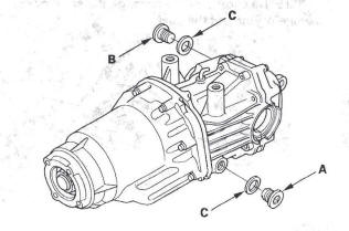
1. Remove the drain plug (A) and the oil filler plug (B) with sealing washers (C).
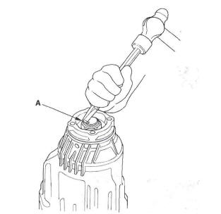
2. Raise the locknut tab (A) from the groove of the clutch guide, making sure the tab completely clears the groove to prevent damaging the clutch guide.
3. Install the companion flange holder (A) and holder handle (B) on the companion flange.
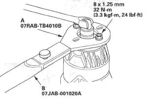
4. Loosen the locknut (A) counterclockwise so its tab (B) comes out from the groove (C) in the clutch guide.
Torque: 147 N.m (15.0 kgf.m, 108 Ibf*ft)
5. Tighten the locknut (A) until its tab (B) aligns with the groove (C).
6. Remove any dirt from inside the groove in the clutch guide, then loosen the locknut.
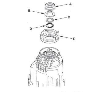
7. Remove the locknut (A), the disc spring washer (B), the back-up ring (C), the O-ring (D), and the companion flange (E).
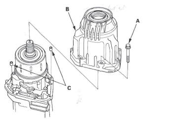
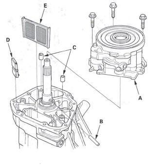
8. Remove the eight mounting bolts (A) in a crisscross pattern in several steps, then remove the torque control differential case (B) and the dowel pins (C).
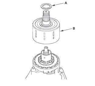
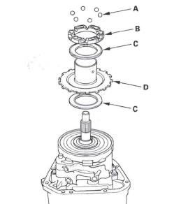
9. Remove the shim (A) and the clutch assembly (B).
10. Remove the six steel balls (A), the base cam (B), the thrust needle bearings (C), and the pressure plate (D).
NOTE: Do not lose the steel balls.
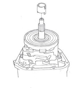
11. Remove the oil pump drives haft.
12. Remove the oil pump body assembly (A), the oil pump pin (B), the dowel pins (C), the magnet (D), and the ATF strainer (E).
READ NEXT:
 Differential Reassembly
Exploded View
Special Tools Required
Holder handle 07JAB-001020A
Companion flange holder 07RAB-TB4010B
1. Apply differential fluid to the rubber pinion of the
ATF strainer (A), then install the A
Differential Mount Replacement
Exploded View
Differential Installation
1. Install rear differential mount assembly A to the
rear differential assembly (B).
2. Jack up the rear differential.
3. Install the new set rings (A) onto t
Driveline/Axle
Special Tools
Oil Seal Driver
Attachment, 52 x 55 mm
Half Shaft Base
Threaded Adapter, 24 x 1.5 mm
Threaded Adapter, 26 x 1.5 mm
Attachment, 35 mm I.D.
Driver
Inner Handle, 30 mm
Oil Seal
SEE MORE:
DTC 32-8x ("x" can be 0 thru 9 or A thru F):
Short to Power in Front Passenger's Side
Airbag Inflator
Special Tools Required
SRS inflator simulator 07SAZ-TB4011A
SRS simulator lead L 070AZ-SNAA300
NOTE: Before doing this troubleshooting procedure,
review SRS Precautions and Procedures.
1. Erase the DTC memory.
2. Turn the ignition switch ON (II), and check that the
SRS indicator comes on for a
Mirrors
Component Location Index
POWER MIRROR ACTUATOR
Replacement
POWER MIRROR
Replacement
MIRROR HOLDER
Replacement
MOUNT
REARVIEW MIRROR
Replacement
Power Mirror Replacement
Special Tools Required
KTC trim tool set SOJATP2014 *
* Available through the American Honda T
