Honda CR-V: Crankshaft and Piston Removal
1. Remove the engine assembly.
2. Remove the transmission.
3. Remove the drive plate.
4. Remove the oil pan.
5. Remove the oil pump.
6. Remove the cylinder head.
7. Remove the baffle plates.
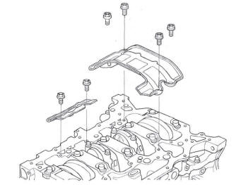
8. Remove the 8 mm bolts.
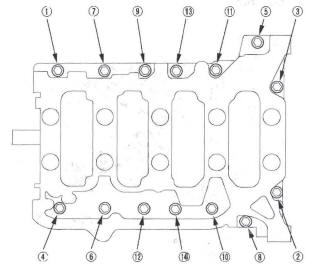
9. Remove the bearing cap bolts. To prevent warpage, unscrew the bolts in sequence 1/3 turn at a time; repeat the sequence until all bolts are loosened.
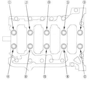
10. Remove the lower block and bearings. Keep all the bearings in order.
11. Remove the rod caps/bearings. Keep all caps/ bearings in order.
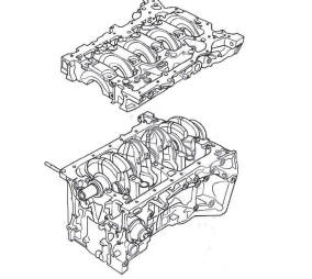
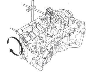
12. Lift the crankshaft out of the engine. Be careful not to damage the journals.
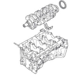
13. Remove the upper bearing halves from the connecting rods, and set them aside with their respective caps.
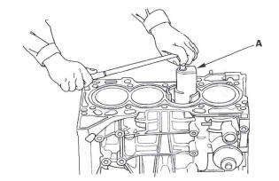
14. If you can feel a ridge of metal or hard carbon around the top of each cylinder, remove it with a ridge reamer (A). Follow the reamer manufacturer's instructions. If the ridge is not removed, it may damage the pistons as they are pushed out.
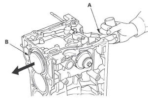
15. Use the wooden handle of a hammer (A) to drive out the piston/connecting rod assembly (B).
16. Reinstall the lower block and the bearings on the engine in the proper order.
17. Reinstall the connecting rod bearings and caps after removing each piston/connecting rod assembly.
18. Mark each piston/connecting rod assembly with its cylinder number to make sure they are reused in the original order.
NOTE: The existing number on the connecting rod does not indicate its position in the engine, it indicates the rod bore size.
Crankshaft Inspection
Out-of-Round and Taper
1. Remove the crankshaft from the engine block.
2. Clean the crankshaft oil passages with pipe cleaners or a suitable brush.
3. Clean the keyway and threads.
4. Measure the out-of-round at the middle of each rod and main journal in two places. The difference between measurements on each journal must not be more than the service limit.
Journal Out-of-Round
Standard (New): 0.005 mm (0.0002 in.) max.
Service Limit: 0.010 mm (0.0004 in.)
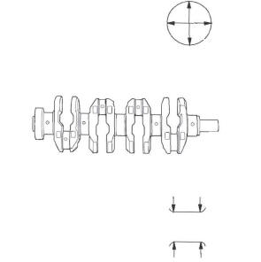
5. Measure the taper at the edges of each rod and main journal. The difference between measurements on each journal must not be more than the service limit.
Journal Taper
Standard (New): 0.005 mm (0.0002 in.) max.
Service Limit: 0.010 mm (0.0004 in.)
Straightness
6. Place the engine block on the surface plate.
7. Clean and install the bearings on the No.1 and No. 5 journals of the engine block.
8. Lower the crankshaft into the block.
9. Measure runout on all main journals. Rotate the crankshaft two complete revolutions. The difference between measurements on each journal must not be more than the service limit.
Crankshaft Total Runout
Standard (New): 0.03 mm (0.0012 in.) max.
Service Limit: 0.04 mm (0.0016 in.)
READ NEXT:
 Block and Piston Inspection
1. Remove the crankshaft and pistons.
2. Check the piston for distortion or cracks.
3. Measure the piston diameter at a point 13 mm
(0.5 in.) from the bottom of the skirt. There are two
standard-siz
Piston, Pin, and Connecting Rod Replacement
Disassembly
1. Remove the piston from the engine block.
2. Apply new engine oil to the piston pin snap rings
(A), and turn them in the ring grooves until the end
gaps are lined up with the cutouts in
Piston Ring Replacement
1. Remove the piston from the engine block.
2. Using a ring expander (A), remove the old piston
rings (B).
3. Clean all ring grooves thoroughly with a squared-off
broken ring or ring groove cleaner
SEE MORE:
Heater Unit/Core
Replacement
SRS components are located in this area. Review the
SRS component locations, and the
precautions and procedures before
doing repairs or service.
1. Make sure you have anti-theft codes for the audio
system and the navigation system (if equipped).
2. Make sure the ignition is OFF, then disconnect the
Connecting Rod and Crankshaft End Play
Inspection
1. Remove the oil pump.
2. Remove the baffle plates (see step 7).
3. Measure the connecting rod end play with a feeler
gauge between the connecting rod and crankshaft.
Connecting Rod End Play
Standard (New): 0.15-0.35 mm (0.006-0.014 in.)
Service Limit:. 0.40 mm (0.016 in.)
4. If the connecting r
