Honda CR-V: System Description
Electronic Control System
The functions of the fuel and emission control systems are managed by the powertrain control module (PCM).
Self-diagnosis
The PCM detects a failure of a signal from a sensor or from another control unit and stores a Temporary DTC or a DTC.
Depending on the failure, a DTC is stored in either the first or the second drive cycle. When a DTC is stored, the PCM turns on the malfunction indicator lamp (MIL) by a signal sent to the gauge via F-CAN.
- One Drive Cycle Detection Method
When an abnormality occurs in the signal from a sensor or from another control unit, the PCM stores a DTC for the failure and turns on the MIL immediately. - Two Drive Cycle Detection Method
When an abnormality occurs in the signal from a sensor or from another control unit in the first drive cycle, the PCM stores a Temporary DTC. The MIL does not come on at this time. If the failure continues in the second drive cycle, the PCM stores a DTC and turns on the MIL.
Fail-safe Function
When an abnormality occurs in the signal from a sensor or from another control unit, the PCM ignores that signal and substitute a pre-programmed value for them that allows the engine to continue running. This causes a DTC to be stored and the MIL to come on.
MIL Bulb Check and Readiness Code Condition
When the ignition switch is turned ON (II), the PCM turns on the MIL via the F-CAN circuit for about 15 to 20 seconds to check the bulb condition. If any readiness codes are not set to complete, the MIL flashes five times. If all readiness codes are set to complete, the MIL goes off.
Self Shut Down (SSD) Mode
After the ignition switch is turned OFF, the PCM stays on (up to 15 minutes). If the PCM connector is disconnected during this time, the PCM may be damaged. To cancel this mode, disconnect the negative cable from the battery or jump the SCS line with the HDS after the ignition switch is turned OFF.
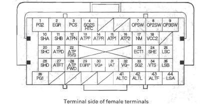
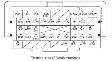
PCM Electrical Connections
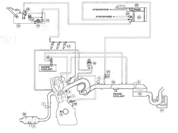
Vacuum Hose Routing
Vacuum Distribution
- AIR FUEL RATIO (A/F) SENSOR (SENSOR 1)
- SECONDARY HEATED OXYGEN SENSOR (SECONDARY HO2S) (SENSOR 2)
- MANIFOLD ABSOLUTE PRESSURE (MAP) SENSOR
- ENGINE COOLANT TEMPERATURE (ECT) SENSOR 1
- MASS AIR FLOW (MAF) SENSOR and INTAKE AIR TEMPERATURE (IAT) SENSOR
- CRANKSHAFT POSITION (CKP) SENSOR
- KNOCK SENSOR
- CAMSHAFT POSITION (CMP) SENSOR B
- CAMSHAFT POSITION (CMP) SENSOR A
- THROTTLE BODY
- INJECTOR
- FUEL PRESSURE REGULATOR
- FUEL FILTER
- FUEL PUMP
- FUEL TANK
- AIR CLEANER
- RESONATOR
- EXHAUST GAS RECIRCULATION (EGR) VALVE and POSITION SENSOR
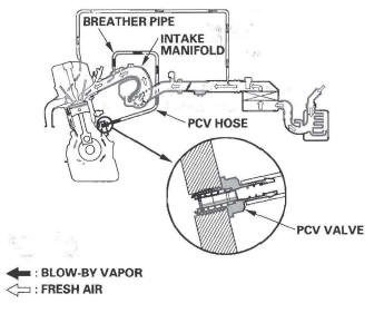
- POSITIVE CRANKCASE VENTILATION (PCV) VALVE
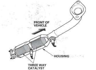
- THREE WAY CATALYTIC CONVERTER
- EVAPORATIVE EMISSION (EVAP) CANISTER PURGE VALVE
- EVAPORATIVE EMISSION (EVAP) CANISTER
- EVAPORATIVE EMISSION (EVAP) CANISTER VENT SHUT VALVE
- FUEL TANK PRESSURE (FTP) SENSOR
- FUEL TANK VAPOR CONTROL VALVE
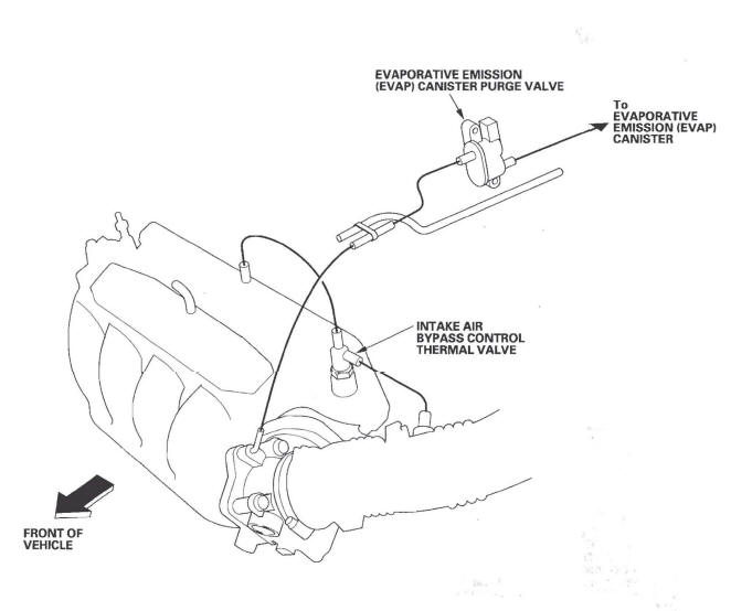
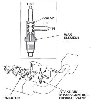
- INTAKE AIR BYPASS CONTROL THERMAL VALVE
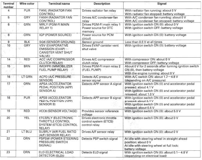
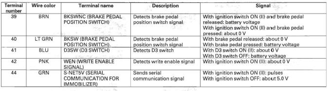
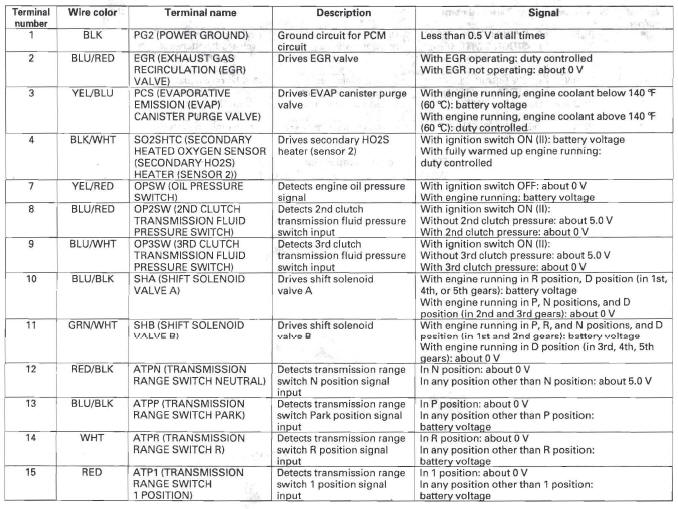
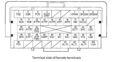
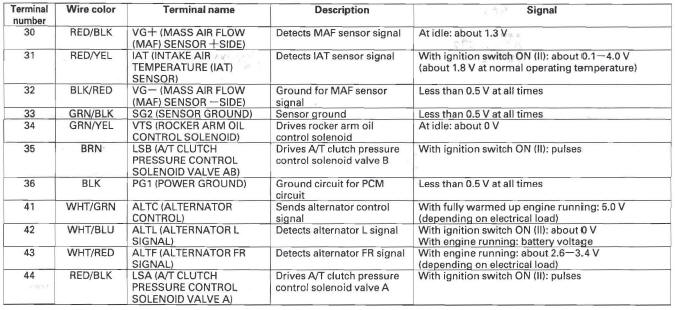
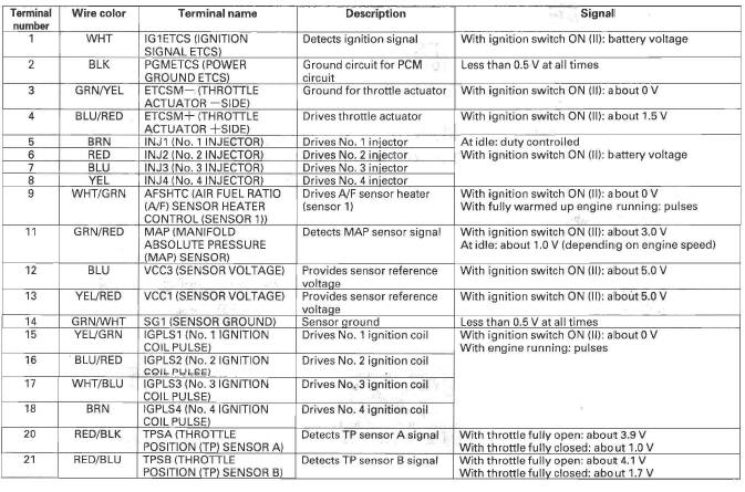
PCM Inputs and Outputs at Connector A ( )
(44P)
)
(44P)
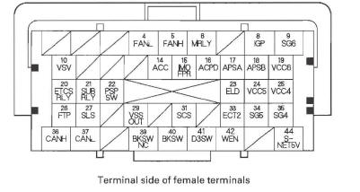
NOTE: Standard battery voltage is about 12 V.
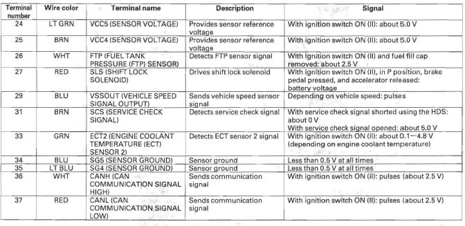
PCM Inputs and Outputs at Connector A ( )
(44P)
)
(44P)
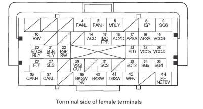
NOTE: Standard battery voltage is about 12 v.
PCM Inputs and Outputs at Connector A ( )
(44P)
)
(44P)

NOTE: Standard battery voltage is about 12 V.
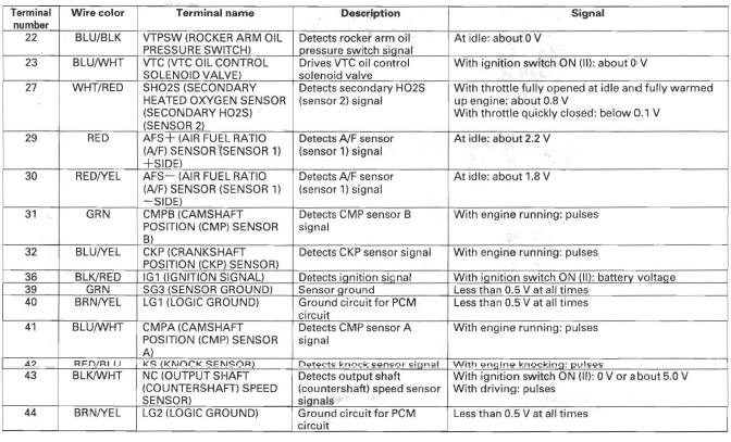
PCM Inputs and Outputs at Connector B ( )
(44P)
)
(44P)
NOTE: Standard battery voltage is about 12 V.
PCM Inputs and Outputs at Connector B ( )
(44P)
)
(44P)
NOTE: Standard battery voltage is about 12 V.
PCM Inputs and Outputs at Connector B ( )
(44P)
)
(44P)
NOTE: Standard battery voltage is about 12 V.
PCM Inputs and Outputs at Connector C ( )
(44P)
)
(44P)
NOTE: Standard battery voltage is about 12 V.
PCM Inputs and Outputs at Connector C ( )
(44P)
)
(44P)

NOTE: Standard battery voltage is about 12 v.
PGM-FI System
The programmed fuel injection (PGM-FI) system is a sequential multiport fuel injection system.
Air Conditioning (A/C) Compressor Clutch Relay
When the PCM receives a demand for cooling from the A/C system, it delays the compressor from being energized, and enriches the mixture to assure smooth transition to the A/C mode.
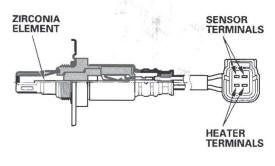
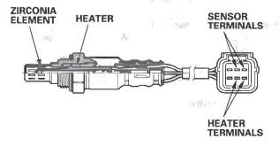
Air Fuel Ratio (A/F) Sensor
The A/F sensor operates over a wide air/fuel range. The A/F sensor is installed upstream of the TWC, and sends signals to the PCM which varies the duration of fuel injection accordingly.
Barometric Pressure (BARD) Sensor
The BARO sensor is inside the PCM. It converts atmospheric pressure into a voltage signal that modifies the basic duration of the fuel injection discharge.
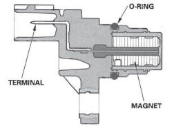
Camshaft Position (CMP) Sensor B
CMP sensor B detects the position of the No.1 cylinder as a reference for sequential fuel injection to each cylinder.
Crankshaft Position (CKP) Sensor
The CKP sensor detects crankshaft speed and is used by the PCM to determine ignition timing and timing for fuel injection of each cylinder as well as detecting engine misfire.
Engine Coolant Temperature (ECT) Sensors 1 and 2
ECT sensors 1 and 2 are temperature dependent resistors (thermistors). The resistance decreases as the engine coolant temperature increases.
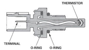
*: This illustration shows ECT sensor 1.
Ignition Timing Control
The PCM contains the memory for basic ignition timing at various engine speeds and manifold absolute pressures. It also adjusts the timing according to engine coolant temperature and intake air temperature.
Injector Timing and Duration
The PCM contains the memory for basic discharge duration at various engine speeds and manifold pressures. The basic discharge duration, after being read out from the memory, is further modified by signals sent from various sensors to obtain the final discharge duration.
By monitoring long term fuel trim, the PCM detects long term malfunctions in the fuel system and sets a diagnostic trouble code (DTC).
Knock Sensor
The knock control system adjusts the ignition timing to minimize knock.
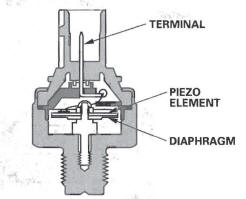
Manifold Absolute Pressure (MAP) Sensor
The MAP sensor converts manifold absolute pressures into electrical signals to the PCM.
Malfunction Indicator Lamp (MIL) Indication (In relation to Readiness Codes)
The vehicle has certain "readiness codes" that are part of the on-board diagnostics for the emissions systems.
If the vehicle's battery has been disconnected or gone dead, if the DTCs have been cleared, or if the PCM has been reset, these codes are reset. In some states, part of the emissions testing is to make sure these codes are set to complete. If all of them are not set to complete, the vehicle may fail the test, or the test cannot be finished.
To check if the readiness codes are set to complete, turn the ignition switch ON (II), but do not start the engine. The MIL will come on for 15-20 seconds. If it then goes off, the readiness codes are complete. If it flashes five times, one or more readiness codes are not complete. To set each code, drive the vehicle or run the engine as described in the procedures.
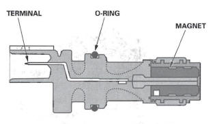
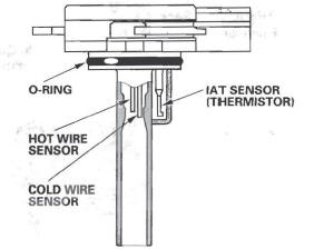
Mass Air Flow (MAF) Sensor/Intake Air Temperature (IAT) Sensor
The mass air flow (MAF) sensor/intake air temperature (IAT) sensor contains a hot wire and a thermistor. It is located in the intake air passage. The resistance of the hot wire and thermistor changes due to intake air temperature and airflow. The control circuit in the MAF sensor controls the current to keep the hot wire at a set temperature. The current is converted to voltage in the control circuit, then output to the PCM.
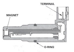
Output Shaft (Counters haft) Speed Sensor
This sensor detects countershaft speed.
Secondary Heated Oxygen Sensor (Secondary HO2S)
The secondary HO2S detects the oxygen content in the exhaust gas downstream of the three way catalytic converter (TWC), and sends signals to the PCM which varies the duration of fuel injection accordingly. To stabilize its output, the sensor has an internal heater.
The PCM compares the HO2S output with the A/F sensor output to determine catalyst efficiency. The secondary HO2S is located on the TWC.
Electronic Throttle Control System
The throttle is electronically controlled by the electronic throttle control system. Refer to the system diagram to see a functional layout of the system.
Idle control: When the engine is idling, the PCM controls the throttle actuator to maintain the proper idle speed according to engine loads.
Acceleration control: When the accelerator pedal is pressed, the PCM opens the throttle valve depending on the accelerator pedal position (APP) sensor signal.
Cruise control: The PCM controls the throttle actuator to maintain set speed when the cruise control is operating.
The throttle actuator takes the place of the cruise control actuator.
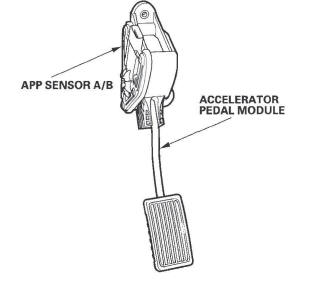
Accelerator Pedal Position (APP) Sensor
As the accelerator pedal position changes, the sensor varies the signal voltage to the PCM.
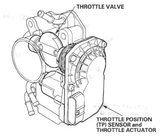
Throttle Body
The throttle body is a single-barrel side draft type. The lower portion of the throttle valve is heated by engine coolant from the cylinder head to prevent icing of the throttle plate.
Idle Control System
When the engine is cold, the A/C compressor is on, the transmission is in gear, the brake pedal is' pressed, the power steering load is high, or the alternator is charging, the PCM controls current to the throttle actuator to maintain the correct idle speed.
Brake Pedal Position Switch
The brake pedal position switch signals the PCM when the brake pedal is pressed.
Power Steering Pressure (PSP) Switch
The PSP switch signals the PCM when the power steering load is high.
Fuel Supply System
Fuel Cutoff Control
During deceleration with the throttle valve closed, current to the injectors is cut off to improve fuel economy at engine speeds over 850 rpm. Fuel cutoff also occurs when the engine speed exceeds 6,700 rpm, regardless of the position of the throttle valve, to protect the engine from over-revving. When the vehicle is stopped, the PCM cuts the fuel at engine speeds over 5,000 rpm. The engine speed of fuel cut is lower on a cold engine.
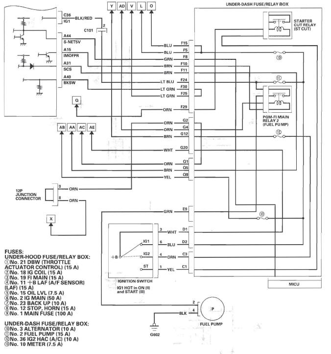
Fuel Pump Control
When the ignition is turned on, the PCM grounds PGM-FI main relay 2 (FUEL PUMP) which feeds current to the fuel pump for 2 seconds to pressurize the fuel system. With the engine running, the PCM grounds PGM-FI main relay 2 (FUEL PUMP) and feeds current to the fuel pump. When the engine is not running and the ignition is on, the PCM cuts ground to PGM-FI main relay 2 (FUEL PUMP) which cuts current to the fuel pump.
PGM-FI Main Relay 1 and 2
PGM-FI main relay 1 is energized whenever the ignition switch is ON (II) to supply battery voltage to the PCM, power to the injectors, and power for PGM-FI main relay 2 (FUEL PUMP). PGM-FI main relay 2 (FUEL PUMP) is energized to supply power to the fuel pump for 2 seconds when the ignition switch is turned ON (II), and when the engine is cranking or running.
VTEC/VTC
- The i-VTEC has a variable valve timing control (VTC) mechanism on the
intake camshaft in addition to the usual
VTEC.
This mechanism improves fuel efficiency and reduces exhaust emissions at all levels of engine speed, vehicle speed, and engine load.
- The VTEC mechanism changes the valve lift and timing by using more than one cam profile.
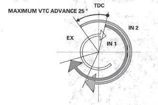
- The VTC changes the phase of the intake camshaft via oil pressure. It changes the intake valve timing continuously.
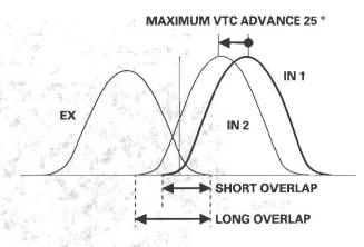
VTC System
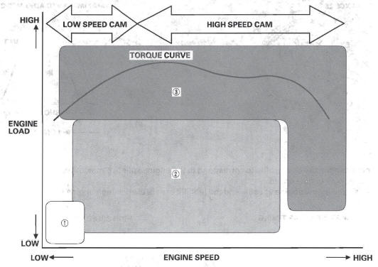
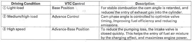
- The VTC system makes continuous intake valve timing changes based on operating conditions.
- Intake valve timing is optimized to allow the engine to produce maximum power.
- Cam angle is advanced to obtain the EGR effect and reduce pumping loss. The intake valve is closed quickly to reduce the entry of the air/fuel mixture into the intake port and improve the charging effect.
- The system reduces the cam advance at idle, stabilizes combustion, and reduces engine speed.
- If a malfunction occurs, the VTC system control is disabled and the valve timing is fixed at the fully retarded position.
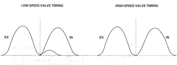
VTEC System
- The VTEC system changes the cam profile to correspond to the engine speed. It maximizes torque at low engine speed and output at high engine speed.
- The low lift cam is used at low engine speeds, and the high lift cam is used at high engine speeds.
VTEC/VTC
System Diagram
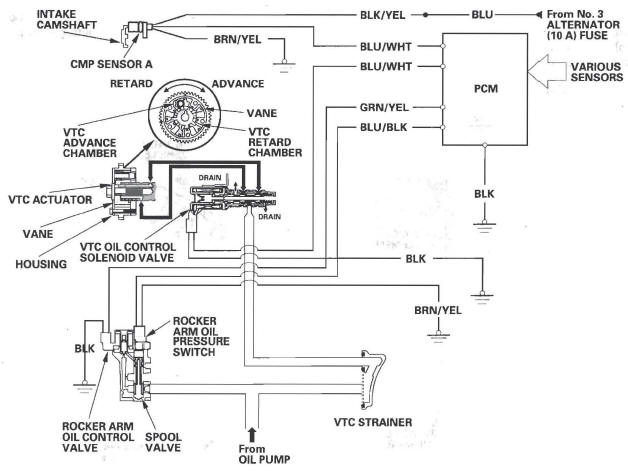
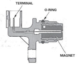
Camshaft Position (CMP) Sensor A
CMP sensor A detects camshaft angle position for the VTC system.
Intake Air System
This system supplies air for engine needs.
Intake Air Bypass Control Thermal Valve
When the engine is cold, the intake air bypass control thermal valve sends air to the injector.
The amount of air is regulated by engine coolant temperature. Once the engine is hot, the intake air bypass control thermal valve closes, stopping air to the injector.
Catalytic Converter System
Three Way Catalytic Converter (TWC)
The TWC converts hydrocarbons (HC), carbon monoxide (CO), and oxides of nitrogen (NOx) in the exhaust gas to carbon dioxide (CO2), nitrogen (N2), and water vapor.
Positive Crankcase Ventilation (PCV) System
The PCV valve prevents blow-by gasses from escaping into the atmosphere by venting them into the intake manifold.
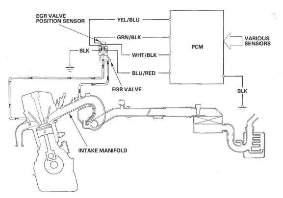
Exhaust Gas Recirculation (EGR) System
Refer to the system diagram to see a functional layout of the system.
EGR Valve
The EGR valve lowers peak combustion temperatures and reduces oxides of nitrogen emissions (NOx) by recirculating exhaust gas through the intake manifold and into the combustion chambers.
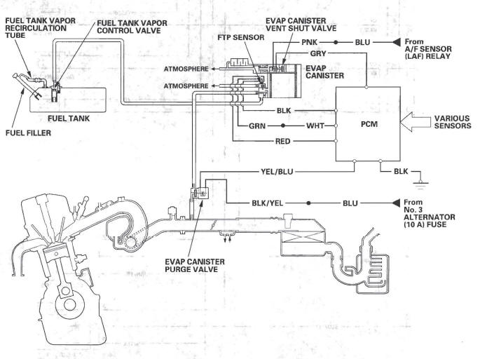
Evaporative Emission (EVAP) Control System
Refer to the system diagram to see a functional layout of the system.
EVAP Canister
The EVAP canister temporarily stores fuel vapor from the fuel tank until it can be purged back into the engine and burned.
EVAP Canister Purge Valve
When the engine coolant temperature is below 140 ºF (60 ºC), the PCM turns off the EVAP canister purge valve which cuts vacuum to the EVAP canister.
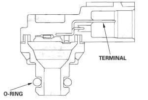
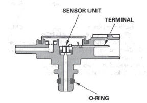
Fuel Tank Pressure (FTP) Sensor
The FTP sensor converts fuel tank absolute pressure into an electrical input to the PCM during the EVAP leak check.
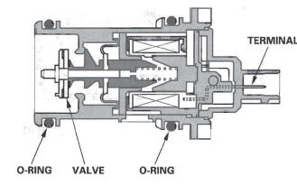
EVAP Canister Vent Shut Valve
The EVAP canister vent shut valve is on the EVAP canister.
The EVAP canister vent shut valve controls the venting of the EVAP canister.
Fuel Cap Warning Message
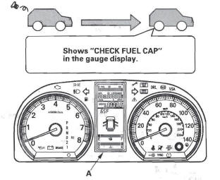
The PCM will detect a loose or missing fuel fill cap as an evaporative system leak and alerts the driver by showing a warning message in the gauge display.
First drive cycle
The first time a leak is detected a "CHECK FUEL CAP" message in the gauge display (A). To scroll to another message, press the select/reset button. The "CHECK FUEL CAP" message will appear each time you restart the engine until the system turns the message off. Turn the engine off then replace or tighten the fuel fill cap until it clicks at least once. The message should go off after several days of normal driving after the fuel fill cap has been tightened or replaced.
To make the message go off (With the HDS)
Procedure
1. Tighten the fuel fill cap until it clicks.
2. Clear the Temporary DTC with the HDS.
3. Verify there is no leak by doing the EVAP FUNCTION TEST in the INSPECTION MENU with the HDS.
To make the message go off (Without the HDS)
Procedure
1. Tighten the fuel fill cap until it clicks.
2. The message should go off after several days of normal driving.
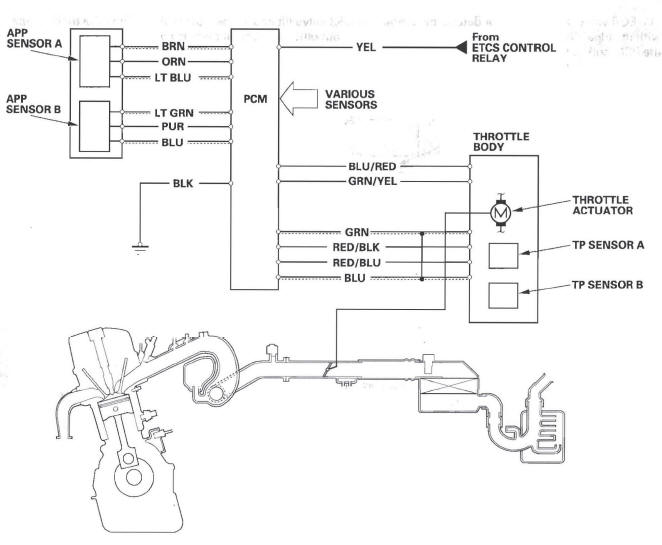
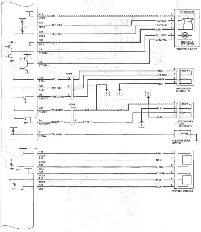
Electronic Throttle Control System Diagram
The electronic throttle control system consists of the throttle actuator, throttle position (TP) sensor A/B, accelerator , pedal position (APP) sensor A/B, electronic throttle control system (ETCS) control relay, and the PCM.
Exhaust Gas Recirculation (EGR) System Diagram
The EGR system reduces oxides of nitrogen (NOx) emissions by recirculating exhaust gas through the EGR valve and the intake manifold into the combustion chambers. The PCM memory includes the ideal EGR valve position for varying operating conditions.
The EGR valve position sensor detects the amount of EGR valve lift and sends it to the PCM. The PCM then compares it with the ideal lift in its memory (based on signals sent from other sensors). If there is any difference between the two, the PCM cuts current to the EGR valve.
Evaporative Emission (EVAP) Control Diagram
The EVAP controls minimize the amount of fuel vapor escaping to the atmosphere. Vapor from the fuel tank is temporarily stored in the EVAP canister until it can be purged from the canister into the engine and burned.
The EVAP canister is purged by drawing fresh air through it and into a port on the intake manifold.
The purging vacuum is controlled by the EVAP canister purge valve, which operates whenever engine coolant temperature is above 140 ºF(60 ºC).
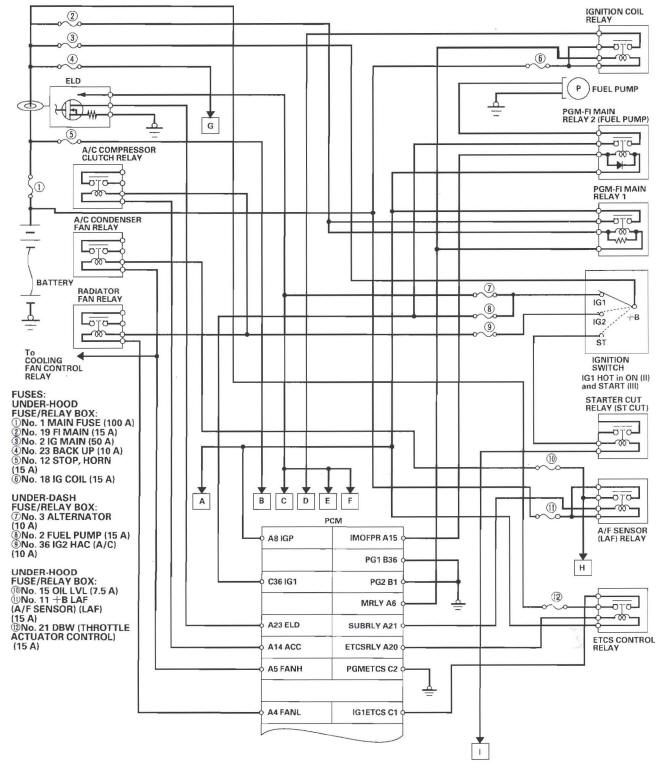
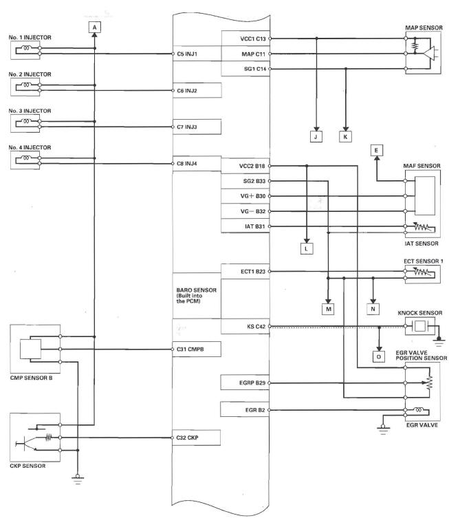
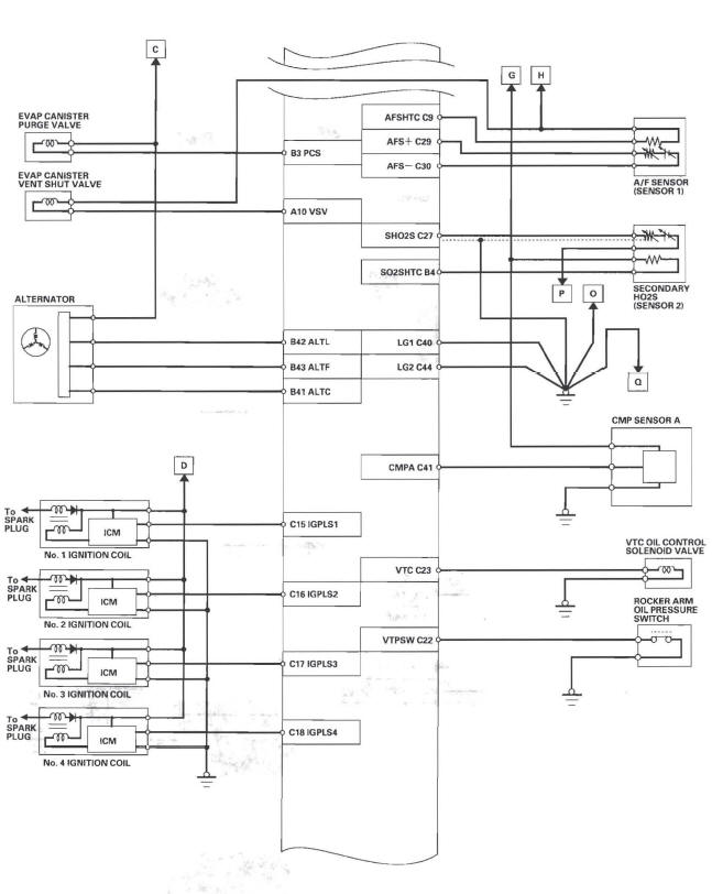
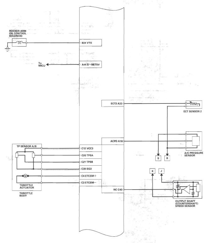
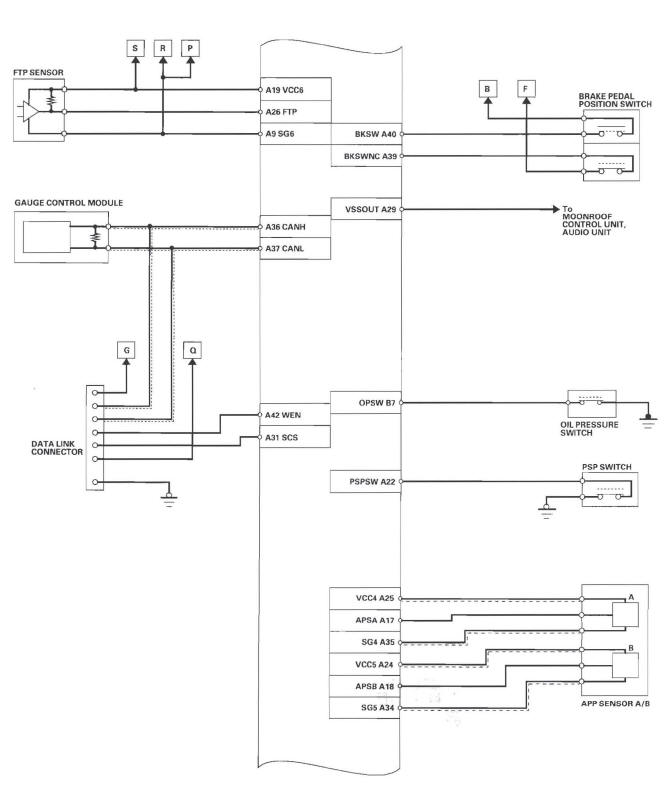
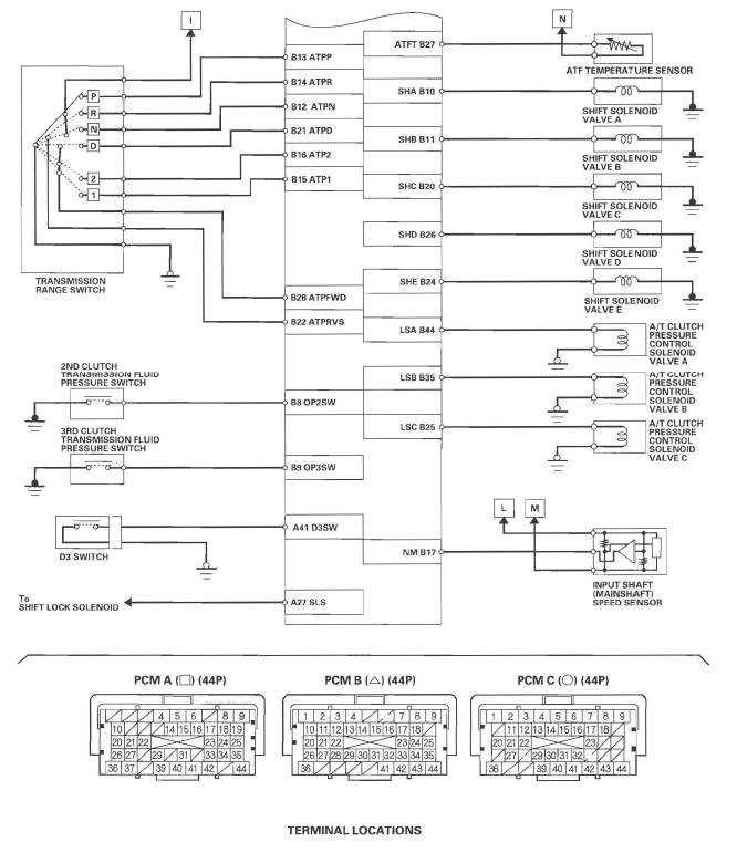
PCM Circuit Diagram
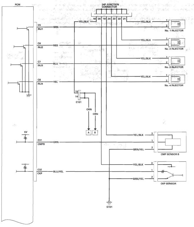
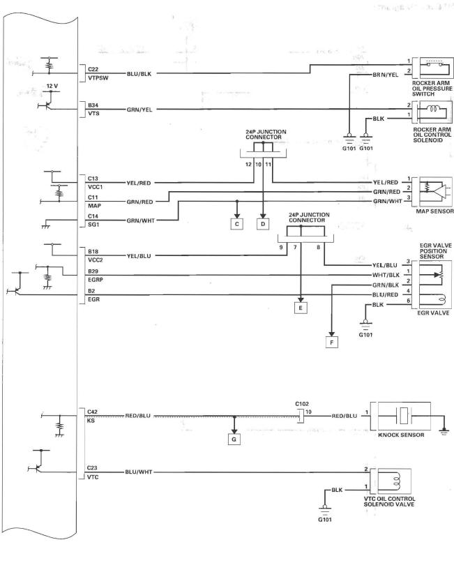
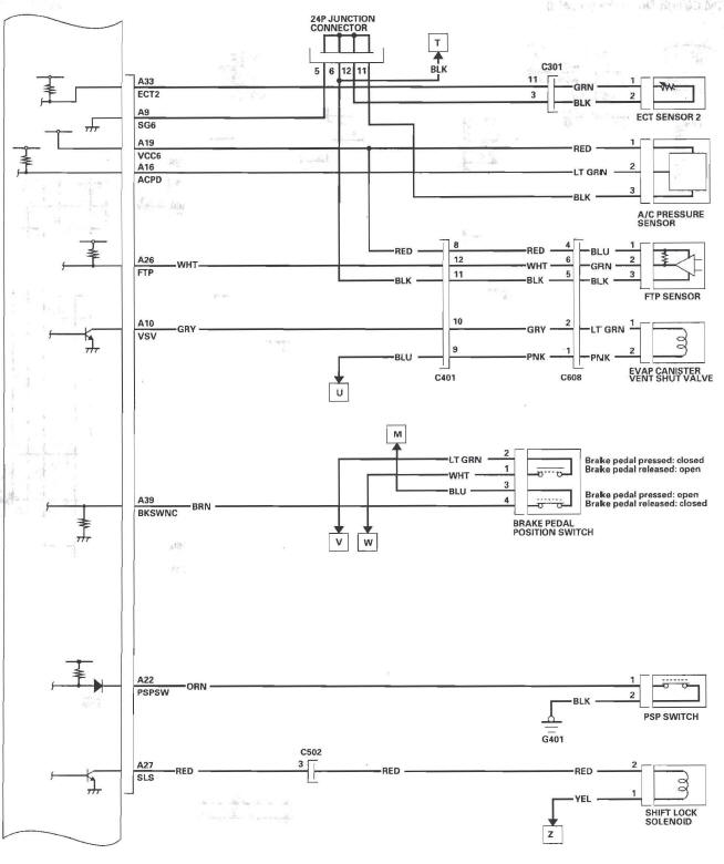
PCM Circuit Diagram
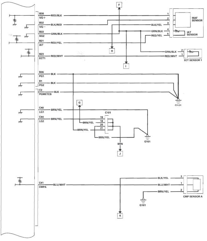
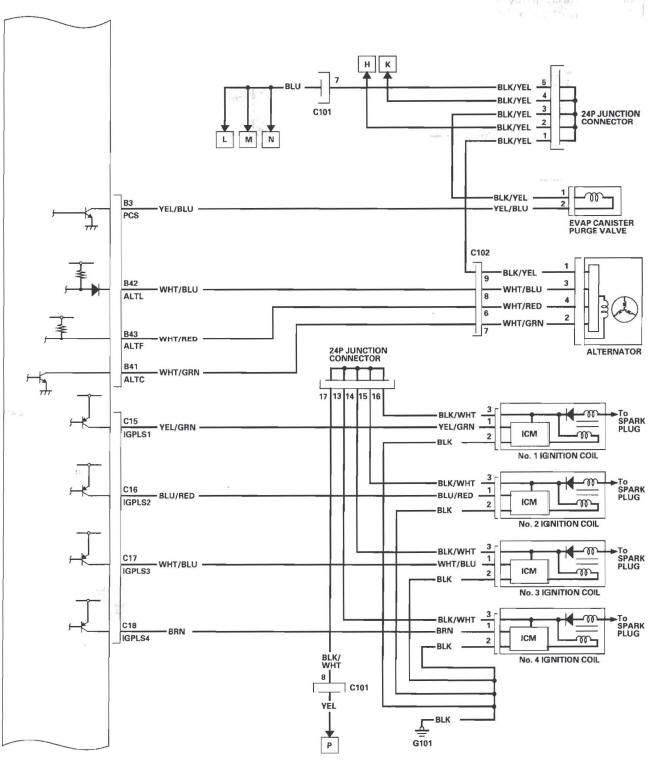
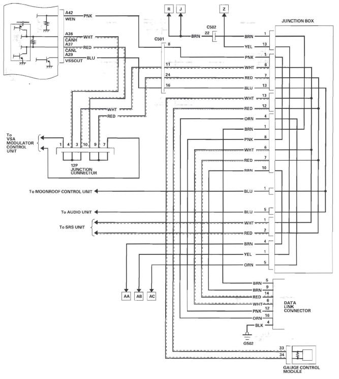
PCM Circuit Diagram
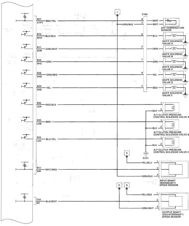
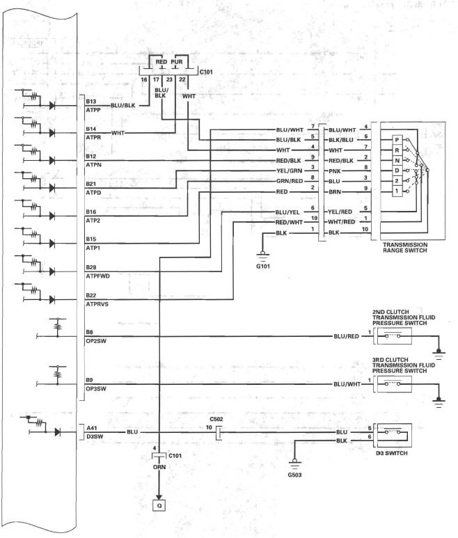
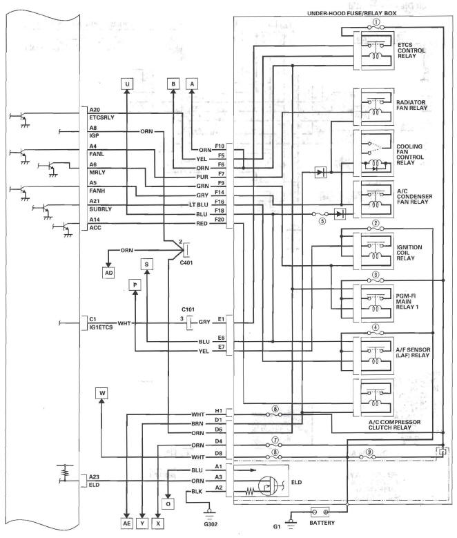
PCM Circuit Diagram
PCM Circuit Diagram
PCM Circuit Diagram
READ NEXT:
 How to Set Readiness Codes
Malfunction Indicator Lamp (MIL) Indication
(In relation to Readiness Codes)
The vehicle has certain "readiness codes" that are part
of the on-board diagnostics for the emissions systems.
If the vehi
PGM-FI System
Component Location Index
CAMSHAFT POSITION (CMP)
SENSOR B (EXHAUST)
OUTPUT SHAFT (COUNTERSHAFT)
SPEED SENSOR
POWERTRAIN CONTROL
MODULE (PCM)
ELECTRICAL LOAD
DETECTOR (E
SEE MORE:
Windshield Wiper
1. MIST
2. OFF
3. INT Intermittent
4. LO Low speed
5. HI High speed
6. Windshield washers
Push the right lever up or down to
select a position.
MIST - The wipers run at high
speed until you release the lever.
OFF - The wipers are not activated.
INT - The wipers operate every
few s
Airbag Service
Your airbag systems are virtually
maintenance free, and there are no
parts you can safely service.
However, you must have your
vehicle serviced if:
An airbag ever inflates. Any airbag
that has deployed must be
replaced along with the control
unit and other related parts. Any
seat bel
