Honda CR-V: Starting System
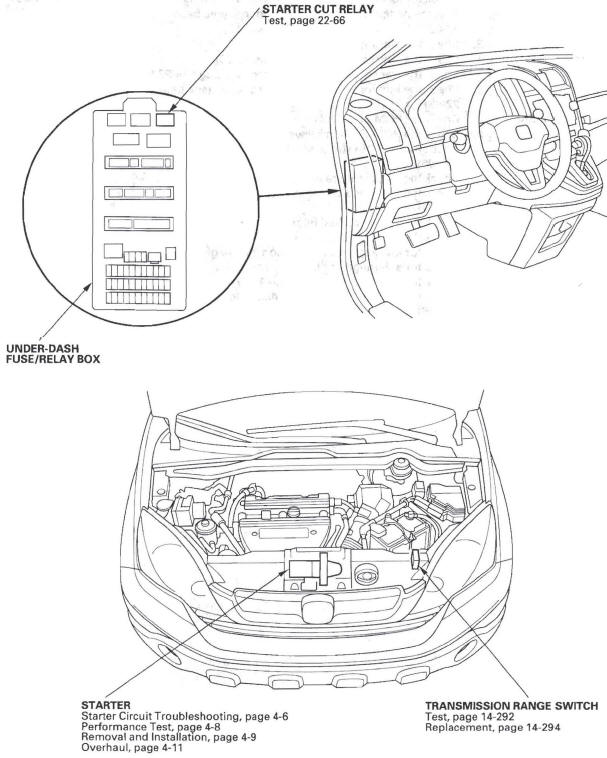
Component Location Index
- STARTER CUT RELAY
- UNDER-DASH FUSE/RELAY BOX
-
STARTER
-
Starter Circuit Troubleshooting
-
Performance Test
-
Removal and Installation
-
Overhaul
-
-
TRANSMISSION RANGE SWITCH
-
Test
-
Replacement
-
Symptom Troubleshooting Index
Engine does not start (does not crank)
- Check for loose battery terminals or connections
- Test the battery for a low state of charge
- Check the starter
- Check the starter cut relay
- Check the transmission range switch
- Check the ignition switch or related circuits
Engine cranks, but does not start
- Check for PGM-FI DTCs
- Check the PGM-FI main relays
- Check for IMMOBI status and function
- Check the fuel pressure
- Check for a plugged or damaged fuel line
- Check for a plugged fuel filter
- Check the throttle body
- Check for low engine compression
- Check for a damaged or broken cam chain
Engine is hard to start
- Check for PGM-FI DTCs
- Check for IMMOBI status and function
- Check the fuel pressure
- Check for a plugged or damaged fuel line
- Check for a plugged fuel filter
Engine cranks slowly
- Check for loose battery terminals or connections
- Test the battery for a low state of charge
- Check the starter for binding
- Check for excessive drag in the engine
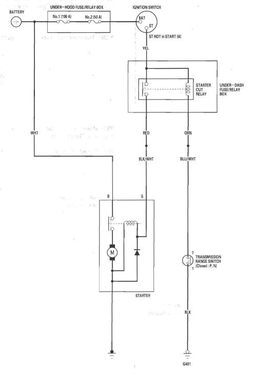
Circuit Diagram
Starter Circuit Troubleshooting
NOTE:
- Air temperature must be between 59 and 100 ºF (15 and 38 ºC) during this procedure.
- After this inspection, you must reset the powertrain control module (PCM), otherwise the PCM will continue to stop the injectors from functioning.
- The battery must be in good condition and fully charged.
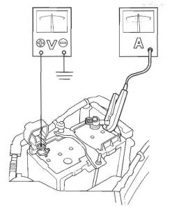
1. Hook up this equipment:
- Ammeter, 0-400 A
- Voltmeter, 0-20 V (accurate within 0.1 V)
2. Connect the HDS to the data link connector (DLC).
3. Turn the ignition switch ON (II).
4. Make sure the HDS communicates with the vehicle and the powertrain control module (PCM). If it doesn't communicate, troubleshoot the DLC circuit.
5. Select PGM-FI, INSPECTION, then ALL INJECTORS OFF on the HDS.
6. Set the parking brake, then with the shift lever in P or N position, turn the ignition switch to START (III).
Does the starter crank the engine normally? YES-The starting system is OK. GO to step 13.
NO-Go to step 7.
7. Check the battery condition. Check electrical connections at the battery, the negative battery cable to body, the engine ground cables, and the starter for looseness and corrosion. Then try cranking the engine again.
Does the starter crank the engine?
YES-Repairing the loose connection corrected the problem. The starting system is OK. Go to step 13.
NO-Based on the following symptoms, take the appropriate action:
- If the starter will not crank the engine at all, go to step 8.
- If the starter cranks the engine erratically or too slowly, go to step 10.
- If the starter does not disengage from the torque
converter ring gear when you release the key,
replace the starter, or remove and disassemble it,
and check for the following:
- Solenoid plunger and switch malfunction
- Dirty drive gear or damaged overrunning clutch
8. Make sure the transmission is in Park or neutral, and set the parking brake. Disconnect the starter subharness 1 P connector (A) from the main wire harness 1 P connector (B). Connect a jumper wire from the battery positive terminal to the starter subharness 1 P connector.
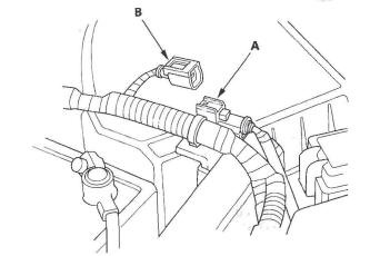
Does the starter crank the engine? YES-Go to step 9.
NO-Check the BLK/WHT wire between the starter subharness 1 P connector and the starter. If the wire is OK, remove the starter, and repair or replace it as necessary.
9. Check the following items in the order listed until you find the open circuit:
- The YEL wire and connectors between the under-dash fuse/relay box and the ignition switch.
- The RED wire and connectors between the under-dash fuse/relay box and the main wire harness 1 P connector.
- The ignition switch.
- The transmission range switch and connector.
- The starter cut relay.
10. While cranking the engine, check the cranking voltage and the current draw.
Is the cranking voltage greater than or equal to 8.5 V and is the current draw less than or equal to 380A?
YES-Go to step 11.
NO-Replace the starter, or remove and disassemble it, and check for these problems:
- Drag in the starter armature
- Shorted armature winding
- Excessive drag in the engine
11. Check the engine speed while cranking the engine.
Is the engine speed above 100 rpm? YES-Go to step 12.
NO-Replace the starter, or remove and disassemble it, and check for these problems:
- Open circuit in the starter armature commutator segments
- Excessively worn starter brushes
- Open circuit in the commutator brushes
- Dirty or damaged helical splines or drive gear
- Faulty drive gear clutch
12. Remove the starter, and inspect its drive gear and the torque converter ring gear for damage. Replace any damaged parts.
13. Select PCM reset to cancel ALL INJECTORS OFF on the HDS.
Starter Performance Test
1. Remove the starter.
2. Connect a fully charged battery to the starter for this test using the thickest (gauge) wire possible (preferably the same gauge as used on the vehicle).
NOTE: To avoid damaging the starter, never leave the battery connected for more than 10 seconds.
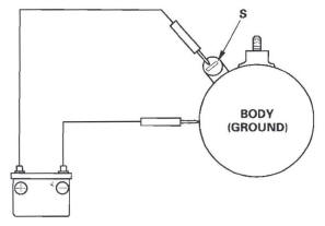
3. Connect the battery as shown. If the starter pinion moves out, it is working properly.
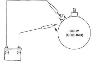
4. Disconnect the battery from the starter body. If the pinion retracts immediately, it is working properly.
5. Firmly clamp the starter in a vise.
6. Connect the starter to the battery as shown, and check that the motor turns and keeps rotating.
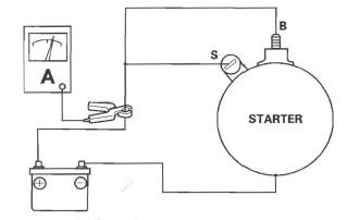
7. If the electric current meets the specification when the battery voltage is at 11.5 V, the starter is working properly.
Specification
Electric Current: 80 A or less
Starter Removal and Installation
Removal
1. Make sure you have the anti-theft code for the audio system and the navigation system (if equipped), then write down the XM radio presets.
2. Disconnect the negative cable from the battery first, then disconnect the positive cable.
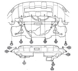
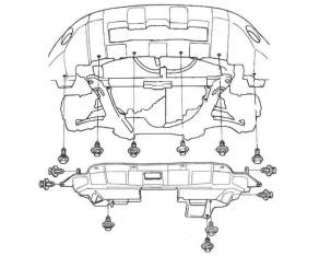
3. Remove the splash shield.
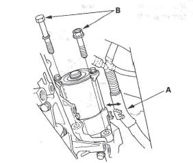
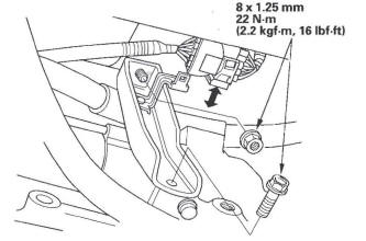
4. Remove the intake manifold bracket.
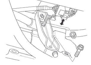
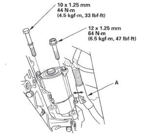
5. Remove the harness clamp (A), and remove the two bolts (B) securing the starter, then remove the starter from the engine.
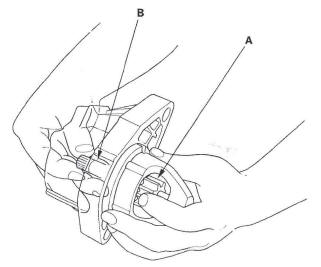
6. Disconnect the starter cable (A) from the B terminal, then disconnect the BLK/WHT wire (B) from the S terminal.
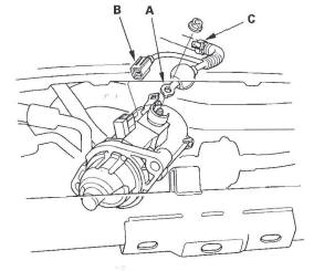
7. Remove the harness clamp (C), then remove the starter.
Installation
1. Install the starter cable (A) and BLK/WHT (B) wire.
Make sure the starter cable crimped side of the ring terminal is facing out.
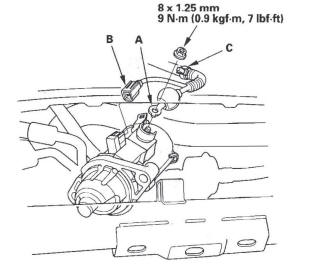
2. Install the harness clamp (C).
3. Install the starter, tighten the bolts, then install the harness clamp (A).
4. Install the intake manifold bracket.
5. Install the splash shield.
6. Connect the positive cable to the battery first. then connect the negative cable.
7. Start the engine to make sure the starter works properly.
8. Enter the anti-theft code for the audio system and the navigation system (if equipped), then enter the XM radio presets.
9. Set the clock.
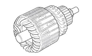
Starter Overhaul
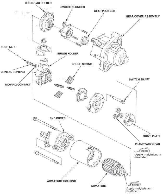
Disassembly/Reassembly
Armature Inspection and Test
1. Remove the starter.
2. Disassemble the starter as shown at the beginning of this procedure.
3. Inspect the armature for wear or damage from contact with the permanent magnet. If there is wear or damage, replace the armature.
4. Check the commutator (A) surface. If the surface is dirty or burnt, resurface it with an emery cloth or a lathe to the following specifications, or recondition with # 500 or # 600 sandpaper (B).
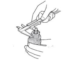
5. Check the commutator diameter. If the diameter is below the service limit, replace the armature.
Commutator Diameter
Standard (New): 28.0-28.1 mm (1.102-1.106 in.)
Service Limit: 27.5 mm (1.083 in.)
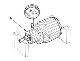
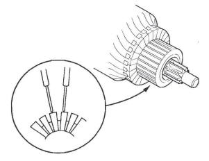
6. Measure the commutator (A) runout.
- If the commutator runout is within the service limit, check the commutator for carbon dust or brass chips between the segments.
- If the commutator runout is not within the service limit, replace the armature.
Commutator Runout
Standard (New): 0.02 mm (0.001 in.) max.
Service Limit: 0.05 mm (0.002 in.)
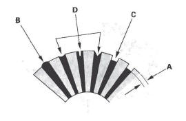
7. Check the mica depth (A). If the mica is too high (B), undercut the mica with a hacksaw blade to the proper depth. Cut away all the mica (C) between the commutator segments. The undercut should not be too shallow, too narrow, or V-shaped (D).
Commutator Mica Depth
Standard (New): 0.40-0.50 mm (0.016-0.020 in.) Service Limit: 0.15 mm , (0.006 in.)
8. Check for continuity between the segments of the commutator. If there is an open circuit between any of the segments, replace the armature.
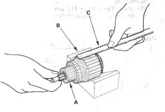
9. Place the armature (A) on an armature tester (B).
Hold a hacksaw blade (C) on the armature core. If the blade is attracted to the core or vibrates while the core is turned, the armature is shorted. Replace the armature.
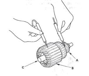
10. Check with an ohmmeter for continuity between the commutator (A) and armature coil core (B), and between the commutator and armature shaft (C). If there is continuity, replace the armature.
Starter Brush Inspection
11. Measure the brush length. If it is shorter than the service limit, replace the brush holder assembly.
Brush Length
Standard (New): 11.1-11.5 mm (0.44-0.45 in.) Service Limit: 4.3 mm (0.17 in.)
Starter Brush Holder Test
12. Check for continuity between the (+) brush (A) and (-) brush (B). If there is continuity, replace the brush holder assembly.
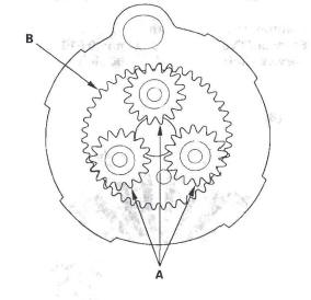
Planetary Gear Inspection
13. Check the planetary gears (A) and ring gear (B).
Replace them if they are worn or damaged.
Overrunning Clutch Inspection
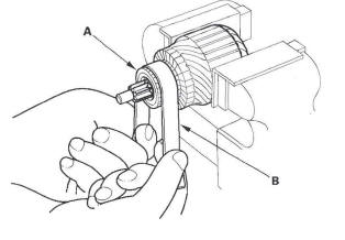
14. While holding the drive gear (A), turn the gear shaft (B) counterclockwise. Check that the drive gear comes out to the other end. If the drive gear does not move smoothly, replace the gear cover assembly.
15. While holding the drive gear, turn the gear shaft clockwise. The gear shaft should turn freely. If the gear shaft does not turn freely, replace the gear cover assembly.
16. If the starter drive gear is worn or damaged, replace the overrunning clutch assembly; the gear is not available separately.
Check the condition of the torque converter ring gear to see if the starter drive gear teeth are damaged.
Starter Reassembly
17. Install the brush into the brush holder, and set the armature (A) in the brush holder (B).
NOTE: To seat the new brushes, slip a strip of # 500 or # 600 sandpaper, with the grit side up, between the commutator and each brush, and smoothly turn the armature. The contact surface of the brushes will be sanded to the same contour as the commutator.
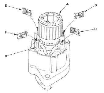
18. While squeezing a spring (C), insert it in the hole on the brush holder, and push it until it bottoms.
Repeat this for the other three springs (D, E, and F).
19. Install the armature and brush holder assembly into the housing.
NOTE: Make sure the armature stays in the holder.
READ NEXT:
 Ignition System
Component Location Index
SPARK PLUG
Inspection
IGNITION COIL
Ignition Timing Inspection
Removal/Installation
Circuit Diagram
Ignition Timing Inspection
1. Conne
Charging System
Component Location Index
CHARGING SYSTEM INDICATOR
(In the gauge control module)
UNDER-HOOD FUSE/RELAY BOX
(Has built-in ELECTRICAL LOAD
DETECTOR [ELD] UNIT)
BATTERY
ALTERNATOR
DRI
Charging System Indicator
Circuit Troubleshooting
1. Turn the ignition switch ON (II).
Does the charging system indicator come on?
YES-Go to step 2.
NO-Go to step 14.
2. Start the engine. Hold the engine speed at
2,000 rpm for 1 minute.
Does the c
SEE MORE:
To Stop Playing a PC Card
To play the radio when a PC card is
playing, press the AM/FM button or
touch the FM1, FM2, AM, XM1, or
XM2 icon. If a disc is in the audio
unit, press the CD/XM button or
touch the CD icon to play the disc. If
a CD or CDs are in the CD changer,
touch the CDC icon to play the
disc(s).
The Starter Operates Normally
In this case, the starter motor’s
speed sounds normal, or even faster
than normal, when you turn the
ignition switch to the START (III)
position, but the engine does not run.
Are you using a properly coded
key? An improperly coded key will
cause the immobilizer system
indicator in t
