Honda CR-V: Ignition System
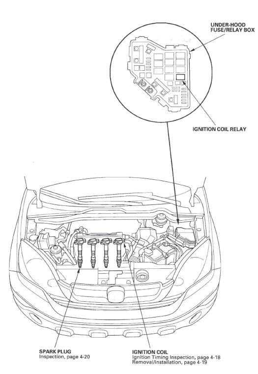
Component Location Index
-
SPARK PLUG
-
Inspection
-
-
IGNITION COIL
-
Ignition Timing Inspection
-
Removal/Installation
-
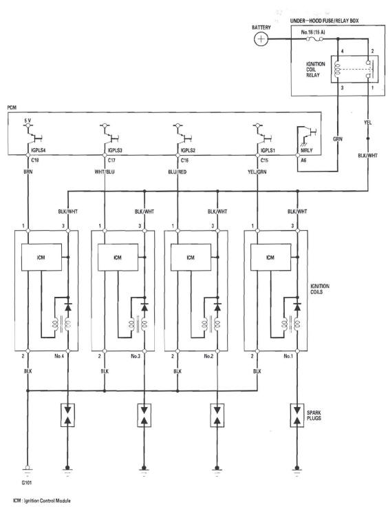
Circuit Diagram
Ignition Timing Inspection
1. Connect the Honda Diagnostic System (HDS) to the data link connector (DLC).
2. Turn the ignition switch ON (II).
3. Make sure the HDS communicates with the vehicle and the powertrain control module (PCM). If it doesn't communicate, troubleshoot the DLC circuit.
4. Start the engine. Hold the engine speed at 3,000 rpm without load (Park or neutral) until the radiator fan comes on, then let it idle.
5. Check the idle speed.
6. Jump the SCS line with the HDS.
7. Connect the timing light to the service loop (white tape).
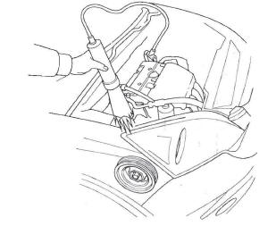
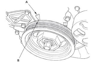
8. Aim the light toward the pointer (A) on the cam chain case. Check the ignition timing under a no load condition (headlights, blower fan, rear window defogger, and air conditioner are turned off).
Ignition Timing:
8 º +- 2 º BTDC (RED mark (B) ) at idle in P or N position
9. If the ignition timing differs from the specification, check the cam timing. If the cam timing is OK, update the PCM, if it does not have the latest software, or substitute a known-good PCM, then recheck. If the system works properly, and the PCM was substituted, replace the original PCM.
10. Disconnect the HDS and the timing light.
Ignition Coil Removal/Installation
1. Remove the ignition coil cover (A), disconnect the ignition coil connectors (B), then remove the ignition coils (C).
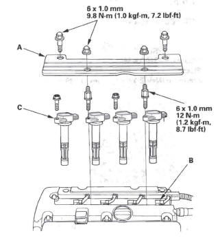
2. Install the ignition coils in the reverse order of removal.
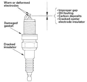
Spark Plug Inspection
1. Remove the spark plugs, and inspect the electrodes and ceramic insulator.
- Burned or worn electrodes may be caused by
these conditions:
- Advanced ignition timing
- Loose spark plug
- Plug heat range too hot
- Insufficient cooling
- Fouled plugs may be caused by these conditions:
- Retarded ignition timing
- Oil in combustion chamber
- Incorrect spark plug gap
- Plug heat range too cold
- Excessive idling/low speed running
- Clogged air cleaner element
- Deteriorated ignition coils
2. If the spark plug electrode is dirty or contaminated, clean the electrode with a plug cleaner.
NOTE:
- Do not use a wire brush or scrape the iridium electrode since this will damage the electrode.
- When using a sand blaster spark plug cleaner, do not clean for more than 20 seconds to avoid damaging the electrode.
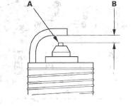
3. Replace the plug at the specified interval, or if the center electrode is rounded (A), or if the spark plug gap (B) is out of specification. Use only the listed spark plugs.
NOTE: Do not adjust the gap of iridium tip plugs.
Spark Plugs
NGK: IZFR6K11
DENSO: SKJ20DR-M11
Electrode Gap
Standard (New): 1.0-1.1 mm (0.039-0.043 in.)
4. Apply a small amount of anti-seize compound to the plug threads, and screw the plugs into the cylinder head, finger-tight. Then torque them to 18 N*m (1.8 kgf*m, 13Ibf*ft).
READ NEXT:
 Charging System
Component Location Index
CHARGING SYSTEM INDICATOR
(In the gauge control module)
UNDER-HOOD FUSE/RELAY BOX
(Has built-in ELECTRICAL LOAD
DETECTOR [ELD] UNIT)
BATTERY
ALTERNATOR
DRI
Charging System Indicator
Circuit Troubleshooting
1. Turn the ignition switch ON (II).
Does the charging system indicator come on?
YES-Go to step 2.
NO-Go to step 14.
2. Start the engine. Hold the engine speed at
2,000 rpm for 1 minute.
Does the c
Alternator and Regulator
Circuit Troubleshooting
1. Make sure the battery connections are good and
the battery is sufficiently charged.
2. Connect a VAT-40 (or equivalent tester), and turn
the selector switch to position 1 (starting).
3. Start the
SEE MORE:
Under-hood/dash Fuse/Relay Box
Under-hood Fuse/Relay Box
Removal and Installation
Removal
1. Make sure you have the anti-theft codes for the
audio and navigation system. If equipped with XM
radio, write down the XM radio presets.
2. Make sure the ignition switch is OFF.
3. Disconnect the negative battery cable, then
disconnect
Automatic Transmission
Special Tools
07HAE-PL50101 may also be used to substitute one of 07LAE-PX40100.
Mainshaft Holder
Attachment, 78 x 90 mm
Clutch Spring Compressor Bolt Assembly
Holder Handle
Oil Seal Driver Attachment
Attachment, 40 x 50 mm
Clutch spring Compressor Attachment
Bearing Installer Attachment
