Honda CR-V: Setting the Clock
On models without navigation system
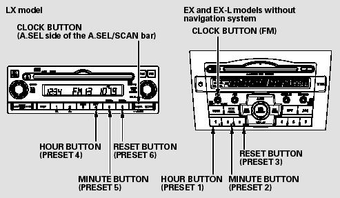
To set the time, press the CLOCK
button until you hear a beep. The
displayed time begins to blink.
Change the hours by pressing the H
(hour) button until the numbers
advance to the desired time. Change
the minutes by pressing the M
(minute) button until the numbers
advance to the desired time.
Press the CLOCK button again to
enter the set time.
You can quickly set the time to the
nearest hour. If the displayed time is
before the half hour, press and hold
the CLOCK button, then press the R
(reset) button to set the time back to
the previous hour. If the displayed
time is after the half hour, the same
procedure sets the time forward to
the beginning of the next hour.

For example:
1:06 will reset to 1:00
1:52 will reset to 2:00
On models with navigation system
The navigation system receives
signals from the global positioning
system (GPS), and the displayed
time is updated automatically by the
GPS. Refer to the navigation system
manual for how to adjust the time.
READ NEXT:
EX model and EX-L model without
navigation system
Next to the outside temperature
indicator of the information display,
a compass indicates which direction
your vehicle is pointed. It indicates
eight directions.
N: North
S: South
E: East
If you see ‘‘- -’’ in the direction
display when you turn the ignition
switch to the ON (II) position, the
compass is self-calibrating.
The compass may need to be
manually calibrate
SEE MORE:
Outline
The rear differential has a real-time 4WD control mechanism that enables 4WD
by transmitting appropriate driving
force from the front wheels to the rear wheels when necessary. It uses a
real-time 4WD dual pump system (DPS) with
a light and compact cam mechanism, and integrates the drive co
Special Tools Required
KTC trim tool set SOJATP2014 *
* Available through the American Honda Tool and
Equipment Program; call 888-424-6857
SRS components are located in this area. Review the SRS component locations and the
precautions and procedures before
doing repairs or service.
NOTE:
Use the a
© 2016-2026 Copyright www.hcrv.net


