Honda CR-V: Receiver/Dryer Desiccant Replacement
NOTE: Install the receiver/dryer as quickly as possible to prevent the system from absorbing moisture from the air.
1. Remove the A/C condenser.
2. Remove the cap (A) from the bottom of the A/C condenser. Remove the O-ring (B) and the desiccant (C).
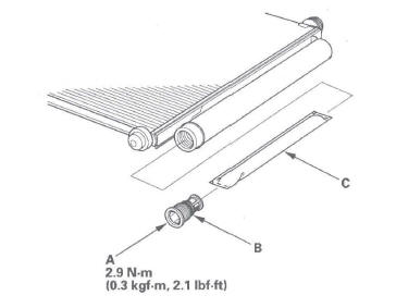
3. Install the receiver/dryer in the reverse order of removal, and note these items:
- Replace the O-rings with new ones, and apply a thin coat of refrigerant oil (SP-10) before installing them. Be sure to use the correct O-rings for HFC-134a (R-134a) to avoid leakage.
- Install the cap to the specified torque. It is made of resin and can be easily stripped.
Refrigerant Recovery
CAUTION
- Air conditioning refrigerant or lubricant vapor can irritate your eyes, nose, or throat.
- Be careful when connecting service equipment.
- Do not breathe refrigerant or vapor.
NOTE:
- If accidental system discharge occurs, ventilate work area before resuming service.
- Additional health and safety information may be obtained from the refrigerant and lubricant manufacturers.
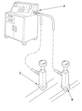
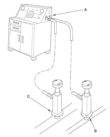
1. Connect an R-134a refrigerant recovery/recycling/ charging station (A) to the high-pressure service port (B) and the low-pressure service port (C), as shown, following the equipment manufacturer's instructions.
2. Measure the amount of refrigerant oil removed from the A/C system after the recovery process is completed. Be sure to put the same amount of new refrigerant oil back into the A/C system before charging.
System Evacuation
CAUTION
- Air conditioning refrigerant or lubricant vapor can irritate your eyes, nose, or throat.
- Be careful when connecting service equipment.
- Do not breathe refrigerant or vapor.
NOTE:
- If accidental system discharge occurs, ventilate work area before resuming service.
- Additional health and safety information may be obtained from the refrigerant and lubricant manufacturers.
1. When an A/C System has been opened to the atmosphere, such as during installation or repair, it must be evacuated using an R-134a refrigerant recovery/recycling/charging station. If the system has been open for several days, the receiver/dryer should be replaced, and the system should be evacuated for several hours.
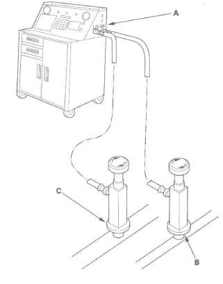
2. Connect an R-134a refrigerant recovery/recycling/ charging station (A) to the high-pressure service port (B) and the low-pressure service port (C), as shown, following the equipment manufacturer's instructions. Evacuate the system.
3. If the low-pressure does not reach more than 93.3 kPa (700 mmHg, 27.6 in.Hg) in 15 minutes, there is probably a leak in the system. Partially charge the system, and check for leaks.
System Charging
CAUTION
- Air conditioning refrigerant or lubricant vapor can irritate your eyes, nose, or throat.
- Be careful when connecting service equipment.
- Do not breathe refrigerant or vapor.
NOTE:
- If accidental system discharge occurs, ventilate work area before resuming service.
- Additional health and safety information may be obtained from the refrigerant and lubricant manufacturers.
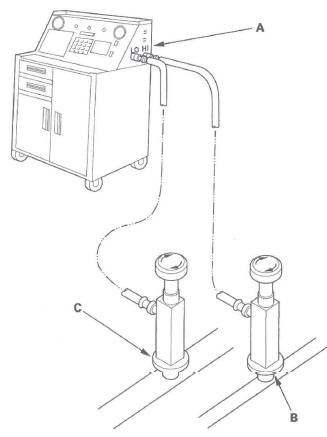
1. Connect an R-134a refrigerant recovery/recycling/ charging station (A) to the high-pressure service port (B) and the low-pressure service port (C), as shown, following the equipment manufacturer's instructions.
2. Evacuate the system.
3. Add the same amount of new refrigerant oil to the system that was removed during recovery. Use only SP-1 0 refrigerant oil.
4. Charge the system with the specified amount of R-134a refrigerant. Do not overcharge the system; the A/C compressor will be damaged.
Select the appropriate units of measure for your refrigerant charging station.
Refrigerant Capacity:
440 to 490 g
0.44 to 0.49 kg
0.97 to 1.08 Ibs
15.5 to 17.3 oz
5. Check for refrigerant leaks.
6. Check the system performance.
Refrigerant Leak Test
Special Tools Required
Leak detector, Honda Tool and Equipment YGK-H-10PM or commercially available
CAUTION
- Air conditioning refrigerant or lubricant vapor can irritate your eyes, nose, or throat.
- Be careful when connecting service equipment.
- Do not breathe refrigerant or vapor
NOTE:
- If accidental system discharge occurs, ventilate work area before resuming service.
- Additional health and safety information may be obtained from the refrigerant and lubricant manufacturers.
1. Connect an R-134a refrigerant recovery/recycling/ charging station (A) to the high-pressure service port (B) and the low-pressure service port (C), as shown, following the equipment manufacturer's instructions.
2. Open the high pressure valve to charge the system to the specified capacity, then close the supply valve, and disconnect the charging station fittings.
Select the appropriate units of measurement for your refrigerant charging station.
Refrigerant Capacity:
440 to 490 g
0.44 to 0.49 kg
0.97 to 1.08 Ibs
15.5 to 17.3 oz
3. Check the system for leaks using an R-134a refrigerant leak detector with an accuracy of 14 g (0.5 oz) per year or better.
4. If you find leaks that require the system to be opened (to repair or replace hoses, fittings, etc.), do a recovery of the system.
5. After checking and repairing leaks, the system must be evacuated.
A/C System Test
Performance Test
CAUTION
- Air conditioning refrigerant or lubricant vapor can irritate your eyes, nose, or throat.
- Be careful when connecting service equipment.
- Do not breathe refrigerant or vapor.
The performance test will help determine if the A/C system is operating within specifications.
NOTE:
- If accidental system discharge occurs, ventilate work area before resuming service.
- Additional health and safety information may be obtained from the refrigerant and lubricant manufacturers.
1. Connect an R-134a refrigerant recovery/recycling/ charging station to the high-pressure service port and the low-pressure service port, following the equipment manufacturer's instructions.
2. Determine the relative humidity and air temperature.
3. Open the glove box. Remove the glove box stop on right side, then let the glove box hang down.
4. Insert a thermometer (A) in the center vent.
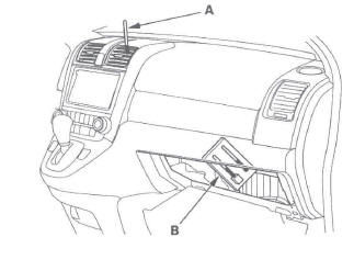
5. Place a thermometer (B) near the blower unit's recirculation inlet duct.
6. Test conditions:
- Avoid direct sunlight.
- Open hood.
- Open front doors.
- Set the temperature control dial to Max Cool, the mode control switch to Vent, and the recirculation control switch to Recirculate.
- Turn the A/C switch ON and the fan switch to Max.
- Run the engine at 1,500 rpm.
- No driver or passengers in vehicle.
7. After running the air conditioning for 10 minutes under the above test conditions, read the delivery temperature from the thermometer in the center vent, the intake temperature near the blower unit, and the discharge (high) and suction (low) pressures on the A/C gauges.
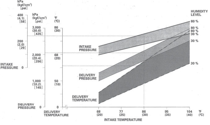
8. Refer to the inspection data.
Inspection data
Example
Intake temperature (dry): 86 F (30 ºC) Humidity level 70 %
Intake temperature (wet): 77.9 F (25.5 ºC)
Delivery temperature: 60.1 F (15.6 ºC)
Delivery pressure: 2,061 kPa (21.0 kgf/cm2) (299 psi)
Intake pressure: 239 kPa (2.4 kgf/cm2) (35 psi)
Results:
Within normal range
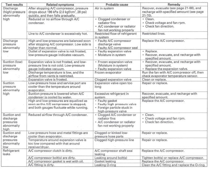
Pressure Test
READ NEXT:
 General Troubleshooting Information
Tips and Precautions
Before Troubleshooting
1. Check applicable fuses in the appropriate fuse/relay
box.
2. Check the battery for damage, state of charge, and
clean and tight connections.
NOTICE
Do
Relay and Control Unit
Locations
Engine Compartment
VSA MODULATOR-CONTROL UNIT
AUXILIARY UNDER-HOOD
RELAY BOX
POWER MIRROR
DEFOGGER RELAY
PCM
RADIATOR FAN RELAY
ELECTRONIC THROTTLE CONTROL SYSTEM (ETCS) CONTROL RELAY
ELD U
SEE MORE:
Steering Wheel Adjustment
Make any steering wheel adjustment
before you start driving.
Adjusting the steering wheel
position while driving may
cause you to lose control of the
vehicle and be seriously injured
in a crash.
Adjust the steering wheel only
when the vehicle is stopped.
1. Push the lever under th
Blower Unit
Removal/Installation
1. Remove the glove box.
2. Disconnect the connector (A), then remove the
connector clip (B), the wire harness clips (C), the
bolts, and the glove box frame (D).
3. Cut the plastic cross brace (A) in the glove box
opening with diagonal cutters in the area shown.
Retain plastic cross brace to be r
