Honda CR-V: Memorizing the Tire Pressure Sensor ID
Special Tools Required
TPMS sensor initializer tool AKS0620006 Available through the American Honda Tool and Equipment program, 888-424-6857.
All four tire pressure sensor IDs must be memorized to the TPMS control unit whenever you do any of these actions:
- Replace the TPMS control unit.
- Replace the tire pressure sensor.
- Substitute a known-good wheel with tire pressure sensor.
NOTE:
- To ensure the control unit memorizes the correct ID, the vehicle with the new sensor must be at least 10 ft (3 m) away from other vehicle have the tire pressure sensors.
- When doing a tire rotation, memorizing the sensors is not needed.
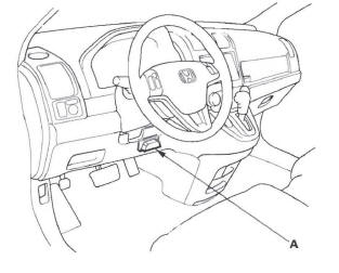
1. With the ignition switch OFF, connect the HDS to the data link connector (DLC) (A) located under the driver's side of the dashboard.
2. Turn the ignition switch ON (II).
3. Make sure the HDS communicates with the vehicle and the TPMS control unit. If it doesn't, troubleshoot the DLC circuit.
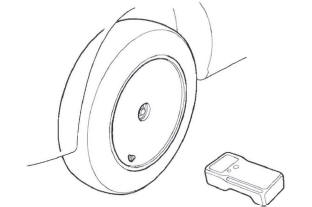
4. Hold the TPMS sensor initializer tool near one wheel, and memorize the pressure sensor ID by following the screen prompts on the HDS.
NOTE:
- If Not defined is shown on the HDS, turn the TPMS sensor initializer tool OFF, rotate the tire 1/4 turn, then turn the TPMS sensor initializer tool ON, and try again. If Not defined is still shown, repeat the procedure in the previous sentence until a response is shown.
- If you turn the ignition switch OFF before memorize all four sensor IDs, the memorizing ID is canceled.
- See the HDS Help menu for specific instructions.
5. Repeat step 4 for each wheel until all four sensor IDs are memorized. When all four IDs are memorized, the low tire pressure indicator blinks.
6. Turn the ignition switch OFF.
7. Test-drive the vehicle at 28 mph (45 km/h) or more for at least 1 minute.
8. Make sure the low pressure indicator does not blink.
9. Turn the ignition switch OFF.
10. Reduce the pressure in one tire until it is less than the appropriate specification.
11. Turn the ignition switch ON (II).
NOTE: If it has been 5 minutes or more since the end of the last test-drive, reactivate the appropriate tire pressure sensor with the TPMS sensor initializer tool.
12. Test-drive the vehicle at 28 mph (45 km/h) or more for at least 1 minute.
13. Make sure the low pressure indicator turns on, then inflate the tire.
14. Repeat steps 9 through 13 for all the other tires.
15. Clear any DTCs with the HDS.
Tire Pressure Sensor Location
Special Tools Required
TPMS sensor initializer tool AKS0620006 Available through the American Honda Tool and Equipment program, 888-424-6857.
This procedure locates where tire pressure sensors 1, 2, 3, and 4 are mounted.
When the activate sensor signal is sent to each wheel using the TPMS sensor initializer tool in sequence, you can locate the tire pressure sensors by the reaction sensor number.
The sensor locations change in these cases:
- Memorizing tire pressure sensor IDs (including replacing the TPMS control unit or the tire pressure sensors).
- Doing a tire rotation.
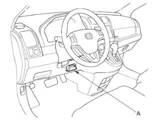
1. With the ignition switch OFF, connect the HDS to the data link connector (DLC) (A) located under the driver's side of the dashboard.
2. Turn the ignition switch ON(II).
3. Make sure the HDS communicates with the vehicle and the TPMS control unit. If it doesn't, troubleshoot the DLC circuit.
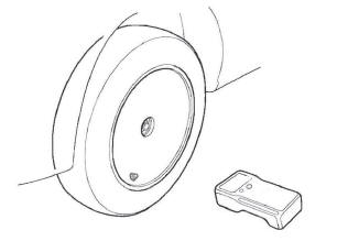
4. Follow the prompts on the HDS to active the tire pressure sensors using the TPMS sensor initializer tool. Start with the left-front (LF) wheel.
NOTE:
- See the HDS Help menu for specific instructions.
- Initialize the wheels in the sequence shown.
INITIALIZATION SEQUENCE:
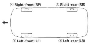
5. Check the HDS screen, and note the active sensor reception order of tire pressure sensors 1, 2, 3, and 4.
NOTE: An example is shown. The sensor signals are received by the TPMS control unit in this order; sensor 1-fourth, sensor 2-second, sensor 3-third, and sensor 4-first.
Example table
6. Note the sensor location for reference.
7. Turn the ignition switch OFF.
DTC Troubleshooting Index
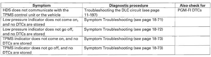
Symptom Troubleshooting Index
System Description
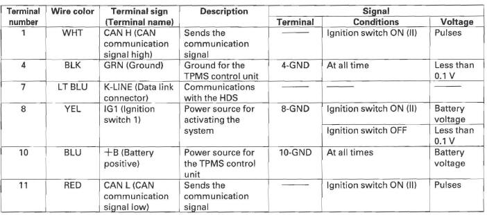
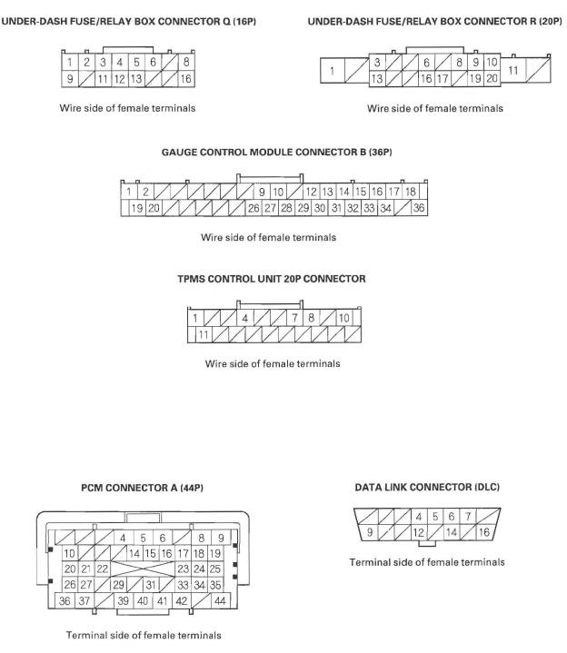
TPMS Control Unit Inputs and Outputs for 20P Connector
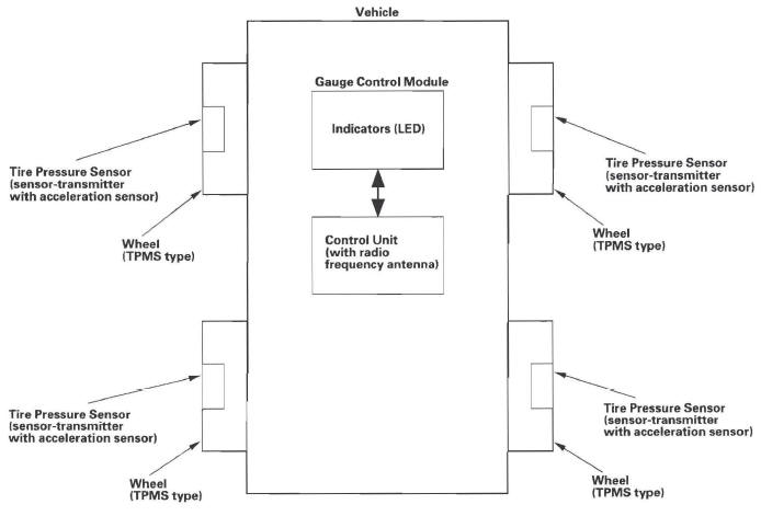
System Structure
Once the vehicle speed exceeds 28 mph (45 km/h), the TPMS control unit monitors all four tires and the system. If it detects low pressure in a tire, it alerts the driver by turning on the low pressure indicator. If it detects a problem in the system, it turns on the TPMS indicator.
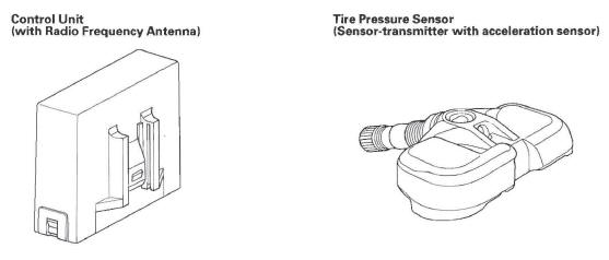
Control unit
Mounted in the middle of the dashboard, the TPMS control unit receives pressure sensor ID signals every time the vehicle speeds exceeds 28 mph (45 km/h). It also receives signals from the transmitters for tire pressure and the sensor condition, and it continuously monitors and controls the system.
Indicators
Two indicators are in the gauge control module: The low pressure indicator comes on when any tire pressure is low, and the TPMS indicator that comes on only if there's a problem with the system.
The low pressure indicator alerts the driver that a tire(s) pressure is low, but does not specify the tire(s) location.
Tire pressure sensor
Each sensor is an integrated unit made up of the tire valve stem, a pressure sensor, and a transmitter. The unit is attached to the inside of the wheel, around the valve stem. The sensor transmits the internal tire information to the control unit once every 60 seconds when the vehicle speed exceeds 28 mph (45 km/h). When the TPMS control unit receives a tire pressure signal that is less than 168 kPa (1.7 kgf/cm2, 24 psi), the control unit then turns on the low pressure indicator. When that tire's pressure is increased to more than 190 kPa (1.9 kgf/cm2, 28 psi), and the vehicle is driven above 28 mph (45 km/h) the transmitter sends the tire pressure signal to the control unit, and then the control unit turns the indicators off.
Do not mix the tire pressure sensor with another TPMS type.
Sensor active:
- When the wheel starts to rotate, the sensor detects the momentum, and switches the sensor to the normal function mode.
- The LF (low frequency) signal of the Snap-on TPMS initializer tool makes
the sensor active though the vehicle is
stopped.
Sensor inactive: When the acceleration sensor detects the wheel is stationary for 5 minutes or more continuously, the tire pressure sensor shuts off automatically, and changes to sleep mode.
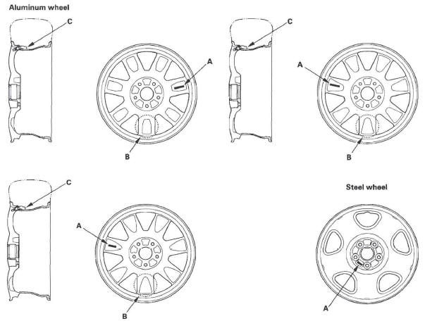
Wheels
TPMS will not work unless TPMS type wheels are installed on the vehicle. The original equipment wheels have a "TPMS" mark (A) on them and counterweights (B) cast into the opposite side of the spoke to counter balance the weight of the tire pressure sensor (C).
NOTE: The vehicle is equipped with either aluminum or steel wheels.
System Communication
- When the vehicle is traveling more than 28 mph (45 km/h), an RF (radio frequency) band wave signal is continuously transmitted from each tire pressure sensor to the control unit.
- When the wheels rotate, the tire pressure sensors' momentum is detected, switching them from sleep mode to normal function mode. After the vehicle is stationary for 5 minutes, the sensors switch from normal function mode back to sleep mode to extend their battery life.
- Each tire pressure sensor has its own 10 to prevent jamming by similar systems on other vehicles. After memorizing all the sensor IDs, the control unit receives only those specific signals.
- An 10 can be memorized manually. The control unit then knows which 10 belongs to each tire pressure sensor. This recurring 10 confirmation prevents any confusion in the system as a result of doing a normal tire rotation.
NOTE: Be careful not to bend the brackets on the TPMS control unit. Misalignment of the control unit could interfere with sending and receiving signals.
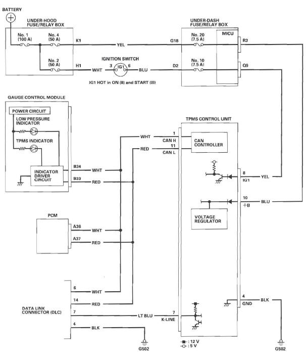
Circuit Diagram
READ NEXT:
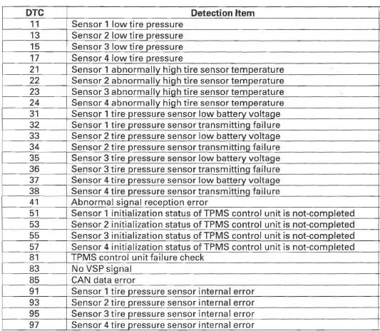
 DTC Troubleshooting
DTC 11, 13, 15, 17: Low Tire Pressure
NOTE: If low tire pressure is detected, the control unit
sets one or more of these DTCs, and turns on the low
pressure indicator. If the low pressure indicator co
Symptom Troubleshooting
Low pressure indicator does not come on,
and no DTCs are stored
1. Turn the ignition switch ON (II).
2. Check the low pressure indicator for several
seconds when the ignition switch is turned ON (II)
Tire Pressure Sensor Replacement
Removal
1. Raise the vehicle, and support it with safety stands in the proper
locations.
2. Remove the wheel with the faulty sensor.
3. Remove the tire valve cap and the valve core, and
let the tir
SEE MORE:
Actual Mileage and EPA Fuel Economy Estimates Comparison.
Fuel economy is not a fixed number.
It varies based on driving conditions,
driving habits and vehicle condition.
Therefore, it is not possible for one
set of estimates to predict fuel
economy precisely for all drivers in
all environments.
The EPA fuel economy estimates
shown in the exam
DTC 91: VSA System
1. Check the brake system for leaks or mechanical
problems.
Is the brake system OK? (No brake fluid leakage,
no air trapped in the brake system, no brake pads
worn out.)
YES-Go to step 2.
NO-Repair the brake system, then recheck.
2. Turn the ignition switch ON (II).
3. Clear the DTC with the HDS
