Honda CR-V: Tire Pressure Sensor Replacement
Removal
1. Raise the vehicle, and support it with safety stands in the proper locations.
2. Remove the wheel with the faulty sensor.
3. Remove the tire valve cap and the valve core, and let the tire deflate.
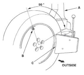
4. Remove any balance weights, and then break the bead loose from the wheel with a commercially available tire changer (A).
NOTICE
Note these items to avoid damaging the tire pressure sensor:
- Do the outside of the wheel first.
- Position the wheel as shown so the valve stem (B) is 90 degrees from the bead breaker (C) as shown.
- Do not position the bead breaker of the tire changer too close to the rim.
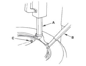
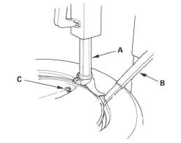
5. Position the wheel so the tire machine (A) and tire iron (B) are next to the valve stem (C) and will move away from it when the machine starts. Then remove the tire from the wheel.
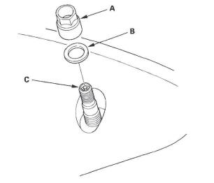
6. Remove the valve stem nut (A) and washer (B), then remove the tire pressure sensor with valve stem (C) from the wheel.
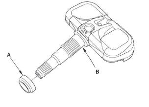
7. Remove and discard the valve stem grommet (A) from the tire pressure sensor (B).
NOTE:
- The valve stem grommet might stay in the wheel; make sure you remove it.
- Always use a new valve stem grommet whenever the tire pressure sensor has been removed from the wheel. When only removing a tire from the wheel, replace the valve stem grommet if it is possible.
Installation
NOTE:
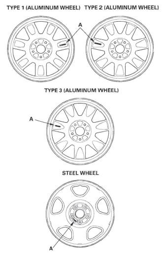
- Use only wheels that have a "TPMS" stamp (A) on them.
- This vehicle may be equipped with either type 1, type 2, or type 3 aluminum wheels, or steel wheels.
1. Before installing the t ire pressure sensor, clean the mating surfaces on the sensor and the wheel.
2. Install the tire pressure sensor (A) and the washer (B) to the wheel (C), and tighten the valve stem nut (D) finger tight. Make sure the pressure sensor is resting on the wheel.
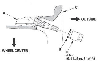
3. Tighten the valve stem nut to the specified torque while holding the tire pressure sensor.
NOTE: Do not use air or electric impact tools to tighten a valve stem nut.
4. Lube the tire bead sparingly, and position the wheel so the tire machine (A) and tire iron (B) are next to the valve stem (C) and will move away from it when the machine starts. Then install the tire onto the wheel.
5. With a dry air source, inflate the tire to 300 kPa (3.1 kgf/cm2, 44 psi) to seat the tire bead to the rim, then adjust the tire pressure.
NOTE: Make sure the tire bead is seated on both sides of the rim uniformly.
6. Check the valve stem nut tightening torque, then install the valve stem cap.
7. Check and adjust the wheel balance, then install the wheels on the vehicle. Torque the wheels to specifications.
8. Remove the jack stands, and lower the jack.
9. Connect the HDS, and memorize the pressure sensor 10(s) using the TPMS sensor initializer tool.
READ NEXT:
 Conventional Brake Components
Special Tools
Brake Caliper Piston Compresor
Component Location Index
BRAKE SYSTEM INDICATOR
Circuit Diagram
Parking Brake Switch Test
Brake Fluid Level Switch Test
BRAKE HOS
Brake System
Brake System Inspection and Test
Inspect the brake system components listed. Repair or replace any parts that
are leaking or damaged.
Component Inspections
Brake System Test
Brake pedal sinks/fades
SEE MORE:
Brake Fluid
Check the fluid level in the brake
fluid reservoir monthly.
Replace the brake fluid according to
the maintenance messages shown on
the information display.
Always use Honda Heavy Duty
Brake Fluid DOT 3. If it is not
available, you should use only DOT 3
or DOT 4 fluid, from a sealed
c
Replacing a Headlight Bulb
Your vehicle has halogen headlight
bulbs. When replacing a bulb, handle
it by its base, and protect the glass
from contact with your skin or hard
objects. If you touch the glass, clean
it with denatured alcohol and a clean
cloth.
Halogen headlight bulbs get very hot
when lit. Oil, p
