Honda CR-V: Symptom Troubleshooting
Low pressure indicator does not come on, and no DTCs are stored
1. Turn the ignition switch ON (II).
2. Check the low pressure indicator for several seconds when the ignition switch is turned ON (II).
Did the indicator come on and then go off? YES-Go to step 3.
NO-Go to step 8.
3. Turn the ignition switch OFF.
4. Check the pressure in all four tires.
Is the tire pressure 168 kPa (1.7 kgf/cm2, 24 psi) or less? YES-Go to step 5.
NO-The system is OK at this time.
5. Turn the ignition switch ON (II).
6. Determine the affected tire location by the tire pressure sensor number, then check the Tire 1. Tire 2, Tire 3, or Tire 4 Pressure Sensor Transmitter Status in the TPMS DATA LIST with the HDS and the TPMS sensor initializer tool.
NOTE: If Not defined is shown on the HDS, turn the TPMS sensor initializer tool OFF, rotate the tire 1/4 turn, then turn the TPMS sensor initializer tool ON, and try again. If Not defined is still shown, repeat the procedure in the previous sentence until a response in shown.
Is NORMAL indicated within one full turn the tire? YES-Go to step 7.
NO- Check that the tire pressure sensor is properly mounted. If necessary, replace the appropriate tire pressure sensor.
7. Check the Tire 1, Tire 2, Tire 3, or Tire 4 Air Pressure in the TPMS DATA LIST with the HDS, and compare with the actual measured tire pressure.
Is the indicated tire pressure on the HDS within 40 kPa (0.4 kgf/cm2, 6 psi) the actual tire pressure? YES-Go to step 8.
NO-Replace the appropriate tire pressure sensor.
8. Wart about 5 seconds with the ignition switch turned ON (lI).
9. Check for gauge DTCs with the HDS.
Is any gauge DTC indicated? YES-Troubleshoot the indicated gauge DTC.
NO-Go to step 10.
10. Turn the ignition switch OFF.
11. Disconnect the TPMS control unit 20P connector.
12. Measure voltage between TPMS control unit 20P connector terminals No.4 and No. B.
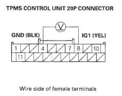
Is there battery voltage? YES-Repair short to power in the wire between the TPMS control unit and the No. 10 (7.5 A) fuse in the under-dash fuse/relay box.
NO- Check for loose terminals and poor connections at the TPMS control unit and G502. If necessary, substitute a known-good TPMS control unit (see page 18-75), and recheck.
Low pressure indicator does not go off, and no DTCs are stored
1. Turn the ignition switch OFF.
2. Disconnect the TPMS control unit 20P connector.
3. Turn the ignition switch ON (II).
4. Check the low pressure indicator for several seconds when the ignition switch is turned ON (II).
Did the indicator come on and then go off? YES-Check for loose terminals and poor connections at the TPMS control unit and G502. If necessary, substitute a known-good TPMS control unit, and recheck.
NO-Do the troubleshooting for the gauge control module. If necessary, substitute a known-good gauge control module, and recheck.
TPMS indicator does not come on, and no DTCs are stored
1. Turn the ignition switch OFF.
2. Disconnect the TPMS control unit 20P connector.
3. Turn the ignition switch ON (II).
4. Check the TPMS indicator for several seconds when the ignition switch is turned ON (II).
Did the indicator come on and then go off? YES-Check for loose terminals and poor connections at the TPMS control unit and G502. If necessary, substitute a known-good TPMS control unit, and recheck.
NO-Do the troubleshooting for the gauge control module, If necessary, substitute a known-good gauge control module, and recheck.
TPMS indicator does not go off, and no DTCs are stored
NOTE: Check for gauge DTCs with the HDS. If gauge DTCs are stored, troubleshoot those DTCs first.
1. Turn the ignition switch ON (II).
2. Check the TPMS indicator for several seconds when the ignition switch is turned ON (II).
Did the indicator come on and then go off? YES-The system is OK at this time.
NO-Go to step 3.
3. Turn the ignition switch OFF.
4. Check the No. 20 (7.5 A) fuse in the under-dash fuse/relay box.
Is the fuse blown? YES-Replace the No. 20 (7.5 A) fuse, and recheck.
NO-Reinstall the fuse, then go to step 5.
5. Check the No. 10 (7.5 A) fuse in the under-dash fuse/relay box.
Is the fuse blown? YES-Replace the No. 10 (7.5 A) fuse, and recheck.
NO-Reinstall the fuse, then go to step 6.
6. Disconnect the TPMS control unit 20P connector.
7. Measure voltage between body ground and TPMS control unit 20P connector terminal No. 10.
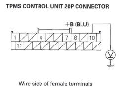
Is there battery voltage? YES-Go to step 8.
NO-Repair open in the wire between the TPMS control unit and the No. 20 (7.5 A) fuse in the under-dash fuse/relay box.
8. Turn the ignition switch ON (II).
9. Measure voltage between body ground and TPMS control unit 20P connector terminal No.8.
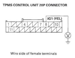
Is there battery voltage? YES-Go to step 10.
NO-Repair open in the wire between the TPMS control unit and the No. 10 (7.5 A) fuse in the under-dash fuse/relay box.
10. Turn the ignition switch OFF.
11. Reconnect the TPMS control unit 20P connector.
12. Turn the ignition switch ON (II).
13. Measure voltage between body ground and TPMS control unit 20P connector terminal No.4.
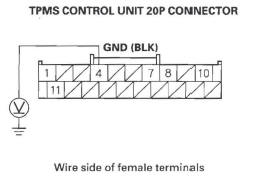
Is there 0.1 V or more? YES-Repair open or high resistance in the wire between the TPMS control unit and body ground (G502).
NO-Do the troubleshooting for the gauge control module. If the gauge control module is OK, check for loose terminals and poor connections at the TPMS control unit. If necessary, substitute a known-good TPMS control unit, and recheck.
TPMS Control Unit Replacement
NOTE: Make sure the TPMS control unit mounting bracket is not bent or twisted as this may affect its communication with the tire pressure sensors.
1. Remove both sides of the front console covers.
2. Remove the dashboard center lower cover.
3. Disconnect the TPMS control unit connector (A).
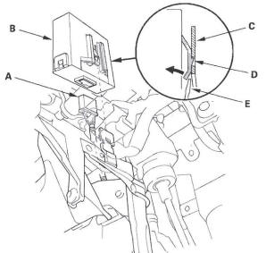
4. Remove the TPMS control unit (B) from the bracket (C).
NOTE: While separating the TPMS control unit from the bracket, release the hook (D) on the TPMS control unit using a flat-tipped screwdriver (E), and push up to release it from the bracket.
5. Install the TPMS control unit in the reverse order of removal.
NOTE: Make sure the TPMS control unit is properly installed. You will hear a click when the TPMS control unit is securely mounted on the bracket.
6. Connect the HDS, and memorize the pressure sensor IDs using the TPMS sensor initializer tool.
READ NEXT:
 Tire Pressure Sensor Replacement
Removal
1. Raise the vehicle, and support it with safety stands in the proper
locations.
2. Remove the wheel with the faulty sensor.
3. Remove the tire valve cap and the valve core, and
let the tir
Conventional Brake Components
Special Tools
Brake Caliper Piston Compresor
Component Location Index
BRAKE SYSTEM INDICATOR
Circuit Diagram
Parking Brake Switch Test
Brake Fluid Level Switch Test
BRAKE HOS
SEE MORE:
Specifications
Dimensions
Weights
Engine
Capacities
Capacities
*1: Excluding the oil remaining in the engine
*2: Including the coolant in the reserve tank and that remaining in the
engine
Reserve tank capacity:
0.16 US gal (0.6 l)
Seating Capacities
Air Conditioning
Lights
Battery
Brake Pedal Position Switch Signal Circuit Troubleshooting
1. Turn the ignition switch ON (II).
2. Check the BRAKE SWITCH in the DATA LIST with
the HDS.
Does it indicate OFF?
YES-Go to step 3.
NO-Inspect the brake pedal position switch.
3. Press the brake pedal, and check the BRAKE
SWITCH in the DATA LIST with the HDS.
Does it change to ON? YES-The bra
