Honda CR-V: Front and Rear Suspension
Special Tools
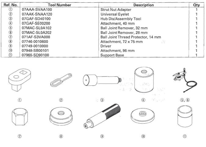
- Strut Nut Adapter
- Universal Eyelet
- Hub Dis/Assembly Tool
- Attachment, 40 mm
- Ball Joint Remover, 32 mm
- Ball Joint Remover, 28 mm
- Ball Joint Thread Protector, 14 mm
- Attachment, 72 x 75 mm
- Driver
- Attachment, 96 mm
- Support Base
Component Location Index
Front Suspension
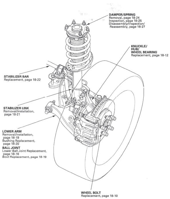
- STABILIZER BAR
- Replacement
- STABILIZER LINK
- Removal/Installation
- LOWER ARM
- Removal/Installation
- Bushing Replacement
- BALL JOINT
- Lower Ball Joint Replacement
- Boot Replacement
- WHEEL BOLT
- Replacement
- KNUCKLE/
HUB/
WHEEL BEARING
- Replacement
- DAMPER/SPRING
- Removal
- Inspection
- Disassembly/Inspection/Reassembly
Rear Suspension
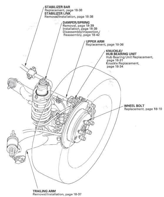
- STABILIZER BAR
- Replacement
- STABILIZER LINK
- Removal/Installation
- DAMPER/SPRING
- Removal
- Installation
- Disassembly/Inspection Reassembly
- UPPER ARM
- Replacement
- KNUCKLE/
HUB BEARING UNIT
- Hub Bearing Unit Replacement
- Knuckle Replacement
- WHEEL BOLT
- Replacement
- TRAILING ARM
- Removal/Installation
Wheel Alignment
The suspension can be adjusted for front camber, front toe, and rear toe. However, each of these adjustments are related to each other. For example, when you adjust camber, the toe will change. Therefore, you must adjust the front wheel alignment whenever you adjust camber or toe.
Pre-Alignment Checks
For proper inspection and adjustment of the wheel alignment, do these checks:
1. Release the parking brake to avoid an incorrect measurement.
2. Make sure the suspension is not modified.
3. Check the tire size and tire pressure.
Tire size: Front/Rear: 225/65R17 102T
Tire pressure: Front/Rear: 210 kPa (2.1 kgf/cm2, 30 psi), cold
4. Check the runout of the wheels and tires.
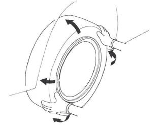
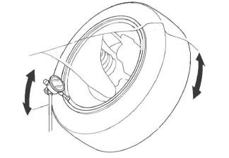
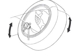
5. Check the suspension ball joints. (Hold a wheel with your hands, and move it up and down and right and left to check for wobbling.)
6. Bounce the vehicle up and down several times to settle the suspension.
Caster Inspection
Use commercially available computerized four wheel alignment equipment to measure wheel alignment (caster, camber, toe, and turning angle). Follow the equipment manufacturer's instructions.
Check the caster angle.
Caster angle: 3 º 02 '+-1 º
- If the measurement is within specifications, measure the camber angle.
- If the measurement is not within specifications, check for bent or damaged suspension components.
Camber Inspection
Use commercially available computerized four wheel alignment equipment to measure wheel alignment (caster, camber, toe, and turning angle). Follow the equipment manufacturer's instructions.
Check the camber angle.
Camber angle:
Front: 0 º 00 ' +-30 '
(Maximum difference between the front right and
left side: 0 º 35 ')
Rear: -1 º00'+-45'
- If the measurement for the front camber is outside the specification, go to front camber adjustment.
- If the measurement for the rear camber is outside the specification, check for bent or damaged suspension components.
Front Camber Adjustment
The front camber can be adjusted by exchanging one or both of the damper pinch bolts with a smaller diameter adjusting bolt. The difference between the adjusting bolt diameter and the pinch bolt hole diameter allows for a small range of adjustment.
1. Raise the front of the vehicle, and support it with safety stands in the proper locations.
2. Remove the front wheels.
3. Loosen the flange bolts (A), and adjust the camber by moving the bottom of the damper within the range of the damper pinch bolt free play.
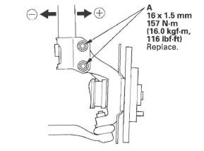
4. Tighten the damper pinch bolts to the specified torque.
5. Reinstall the front wheels. Lower the front of the vehicle to the ground, and bounce the front of the vehicle up and down several times to settle the suspension.
6. Measure the camber angle.
- If the measurement is within specification, measure the toe.
- If the measurement is not within specification, go to step 7.
7. Raise the front of the vehicle, and support it with safety stands in the proper locations.
8. Remove the front wheels.
9. Replace the damper pinch bolts with the adjusting bolts (A), and adjust the camber angle.
NOTE:
- The camber angle can be adjusted up to +-25 ' (center of tolerance) by replacing one damper pinch bolt with the adjusting bolt.
- The camber angle can be adjusted up to 50 ' by replacing both damper pinch bolts with the adjusting bolts.
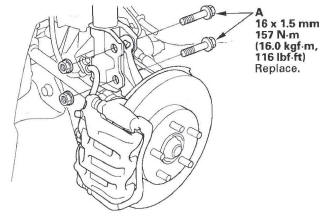
10. Tighten the adjusting bolts to the specified torque value.
11. Install the front wheels.
12. Lower the vehicle to the ground, and bounce the front of the vehicle up and down several times to settle the suspension.
13. Measure the camber angle. If the camber angle is not within specification, repeat steps 7 through 12 to readjust the camber angle. If the camber measurement is correct, measure toe-in, and adjust it if necessary.
Front Toe Inspection/Adjustment
Use commercially available computerized four wheel alignment equipment to measure wheel alignment (caster, camber, toe, and turning angle). Follow the equipment manufacturer's instructions.
1. Center the steering wheel spokes, and install a steering wheel holder tool.
2. Check the toe with the wheels pointed straight ahead.
Front toe-in: 0+-2 mm (0+-0.08 in.)
- If adjustment is required, go to step 3.
- If no adjustment is required, go to rear toe inspection/adjustment.
3. Loosen the tie-rod locknuts (A) while holding the flat surface sections (B) of the tie-rod end with a wrench, and turn both tie-rods (C) until the front toe is within specifications.
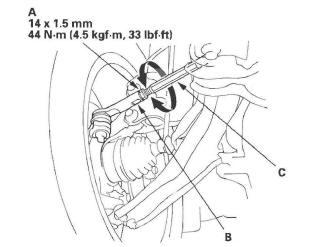
4. After adjusting, tighten the tie-rod locknuts.
Reposition the rack-end boot if it is twisted or displaced.
5. Go to rear toe inspection/adjustment.
Rear Toe Inspection/Adjustment
Use commercially available computerized four wheel alignment equipment to measure wheel alignment (caster, camber, toe, and turning angle). Follow the equipment manufacturer's instructions.
1. Release the parking brake to avoid an incorrect measurement.
2. Check the toe.
- If adjustment is required, go to step 3.
- If no adjustment is required, remove the alignment equipment.
3. Hold the adjusting bolt (A) on the trailing arm (B), and remove the self-locking nut (C).
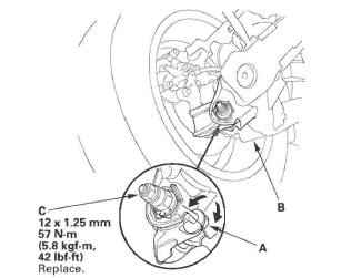
4. Replace the self-locking nut with a new one, and lightly tighten it.
NOTE:
- Always use a new self-locking nut whenever it has been loosened.
- Reassemble the adjusting bolt and camplate with the eccentric facing up.
5. Adjust the rear toe by turning the adjusting bolt until the toe is correct.
6. Tighten the new self-locking nut while holding the adjusting bolt.
Turning Angle Inspection
Use commercially available computerized four wheel alignment equipment to measure wheel alignment (caster, camber, toe, and turning angle). Follow the equipment manufacturer's instructions.
1. Turn the wheel right and left while applying the brake, and measure the turning angle of both wheels.
Turning angle:
Inward wheel: 36º 29' +-2º
Outward wheel: 31º 14' (reference)
2. If the turning angle is not within the specifications, check for bent or damaged suspension components.
Wheel Bearing End Play Inspection
1. Raise the vehicle, and support it with safety stands in the proper locations.
2. Remove the wheels.
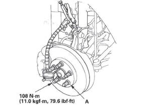
3. Install suitable flat washers (A) and the wheel nuts.
Tighten the nuts to the specified torque to hold the brake disc or disc/drum securely against the hub.
Front
Rear
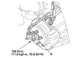
4. Attach the dial gauge. Place the dial gauge against the hub flange.
5. Measure the bearing end play by moving the disc or disc/drum inward and outward.
Front/Rear:
Standard: 0-0.05 mm (0-0.002 in.)
6. If the bearing end play measurement is more than the standard, replace the wheel bearing or hub bearing unit.
Wheel Runout Inspection
NOTE: When measuring the front wheel runout, turn the back side of the wheel slowly by hand.
1. Raise the vehicle, and support it with safety stands in the proper locations.
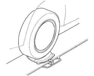
2. Check for bent or deformed wheels.
3. Set up the dial gauge as shown, and measure axial runout by turning the wheel.
Front and rear wheel axial runout:
Standard:
Steel wheel: 0-1.0 mm (0-0.04 in.)
Aluminum wheel: 0-0.7 mm (0-0.03 in.)
Service limit: 2.0 mm (0.08 in.)
4. Reset the dial gauge to the position shown, and measure the radial runout.
Front and rear wheel radial runout:
Standard:
Steel wheel: 0-1.0 mm (0-0.04 in.)
Aluminum wheel: 0-0.7 mm (0-0.03 in.)
Service limit: 1.5 mm (0.06 in.)
5. If the wheel runout is not within the specification, check the wheel bearing end play, and make sure the mating surfaces on the brake disc or disc/drum and the inside of the wheel are clean.
6. If the bearing end play is within the specification but the wheel runout is more than the service limit, replace the wheel.
Wheel Bolt Replacement
NOTICE
- Do not use a hammer or air or electric impact tools to remove and install the wheel bolts.
- Be careful not to damage the threads of the wheel bolts.
1. Remove the front hub or rear hub bearing unit: front, rear.
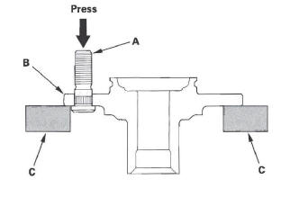
2. Separate the wheel bolt (A) from the hub (B) using a hydraulic press. Support the hub with hydraulic press attachments (C) or equivalent tools.
NOTE:
- Before installing the new wheel bolt, clean the mating surface on the bolt and the hub.
- The illustration shows a front hub.
3. Insert the new wheel bolt into the hub while aligning the splined surfaces on the hub hole with the wheel bolt.
NOTE:
- Degrease all around the wheel bolt and the threaded section of the nut.
- Make sure the wheel bolt is installed vertically in relation to the hub disc surface.
- Do not install the nut and washers that have been used as tools on a vehicle.
4. Press in the wheel bolt using a hydraulic press.
Support the hub with hydraulic press attachments or equivalent tools.
5. Install the front hub or rear hub bearing unit: front, rear.
NOTE: If you cannot tighten the wheel nut to the specified torque value when installing the wheel, replace the front hub or rear hub bearing unit as an assembly.
Ball Joint Removal
Special Tools Required
- Ball joint remover, 32 mm 07MAC-SL0A102
- Ball joint remover, 28 mm 07MAC-SL0A202
NOTICE
Always use a ball joint remover to disconnect a ball joint. Do not strike the housing or any other part of the ball joint connection to disconnect it.
07MAC-SL0A102 or 07MAC-SL0A202
1. Install a hex nut (A) or ball joint thread protector onto the threads of the ball joint (B). Make sure the nut is flush with the ball joint pin end to prevent damage to the thread end of the ball joint pin.
2. Apply grease to the ball joint remover on the areas shown (A). This will ease installation of the tool and prevent damage to the pressure bolt (B) threads.
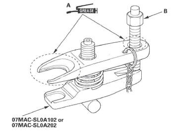
3. Loosen the pressure bolt (A), and install the ball joint remover as shown. Insert the jaws carefully, making sure not to damage the ball joint boot.
Adjust the jaw spacing by turning the adjusting bolt (B).
NOTE: Fasten the safety chain (C) securely to a suspension arm or the subframe (D). Do not fasten it to a brake line or wire harness.
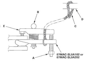
4. After adjusting the adjusting bolt, make sure the head of the adjusting bolt is in the position shown to allow the jaw (E) to pivot.
5. With a wrench, tighten the pressure bolt until the ball joint pin pops loose from the ball joint pin hole.
If necessary, apply penetrating type lubricant to loosen the ball joint pin.
NOTE: Do not use pneumatic or electric tools on the pressure bolt.
6. Remove the ball joint remover, then remove the nut from the end of the ball joint pin, and pull the ball joint out of the ball joint pin hole. Inspect the ball joint boot, and replace it if damaged.
READ NEXT:
 Knuckle/Hub/Wheel Bearing Replacement
Exploded View
Special Tools Required
Hub dis/assembly tool 07GAF-SD40100
Ball joint remover, 32 mm 07MAC-SL0A102
Ball joint remover, 28 mm 07MAC-SL0A202
Ball joint thread protector, 14 mm 071AF-
Lower Ball Joint Replacement
Special Tools Required
Ball joint remover, 32 mm 07MAC-SL0A 102
Ball joint thread protector, 14 mm 071AF-S3VA000
1. Remove the front wheel.
2. Remove the flange bolt and flange nuts from the
lowe
SEE MORE:
Phone Setup
This command group is available for
paired cell phones.
Phone pairing tips
You cannot pair your phone while
the vehicle is moving.
Your phone must be in discovery
or search mode to pair. Refer to
your phone’s manual.
Up to six phones can be paired.
Your phone’s battery may drain
f
Engine Coolant
Adding Engine Coolant
If the coolant level in the reserve
tank is at or below the MIN line, add
coolant to bring it up to the MAX line.
Inspect the cooling system for leaks.
Always use Honda Long-life Antifreeze/
Coolant Type 2. This coolant
is pre-mixed with 50 percent
antifreeze and
