Honda CR-V: DTC P2122: Accelerator Pedal Position (APP) Sensor A (Throttle Position Sensor D) Circuit Low Voltage Input
NOTE: Before you troubleshoot, record all freeze data and any on-board snapshot, and review General Troubleshooting Information.
1. Clear the DTC with the HDS.
2. Turn the ignition switch ON.
3. Check whether DTC P2122 is indicated in the DTCs/ Freeze Data in PGM-FI Mode Menu with the HDS.
Is DTC P2122 indicated in the PGM-FI system? YES-Troubleshoot for DTC P2122 in the PGM-FI System.
NO-Go to step 4.
4. Check whether DTC P2122 is indicated in the DTCs/ Freeze Data in A/T Mode Menu with the HDS.
Is DTC P2122 indicated? YES-Go to step 5.
NO-Intermittent failure, the system is OK at this time.
5. Update the A/T software in the PCM if it does not have the latest software (see page 14-9), or substitute a known-good PCM.
6. Turn the ignition switch ON (II).
7. Check for DTC(s) in the DTCs/Freeze Data in A/T Mode Menu with the HDS.
Is DTC P2122 indicated? YES-If the PCM was updated, substitute a known-good PCM (see page 14-10), then recheck. If the PCM was substituted, go to step 1.
NO-Go to step 8.
8. Monitor the OBD STATUS for P2122 in the DTCs/ Freeze Data in A/T Mode Menu for a pass/fail.
Does the HDS indicate PASSED? YES-If the PCM was updated, troubleshooting is complete. If the PCM was substituted, replace the original PCM (see page 11-219). If any other DTCs were indicated on step 7, go to the indicated DTC's troubleshooting.
NO-If the HDS indicates FAILED, check for poor connections and loose terminals at accelerator pedal position sensor A and the PCM. If the PCM was updated, substitute a known-good PCM (see page 14-10), then recheck. If the PCM was substituted, go to step 1. If the HDS indicates NOT COMPLETED, return to step 6 and recheck.
DTC P2123: Accelerator Pedal Position (APP) Sensor A (Throttle Position Sensor D) Circuit High Voltage Input
NOTE: Before you troubleshoot, record all freeze data and any on-board snapshot, and review General Troubleshooting Information (see page 14-4), 1, Clear the DTC with the HDS, 2, Turn the ignition switch ON (II), 3. Check whether DTC P2123 is indicated in the DTCs/ Freeze Data in PGM-FI Mode Menu with the HDS, Is DTC P2123indicated in the PGM-FI system? YES-Troubleshoot for DTC P2123 in the PGM-FI System.
NO-Go to step 4.
4. Check whether DTC P2123 is indicated in the DTCs/ Freeze Data in A/T Mode Menu with the HDS.
Is DTC P2123 indicated? YES-Go to step 5, NO-Intermittent failure, the system is OK at this time.
5. Update the A/T software in the PCM if it does not have the latest software (see page 14-9), or substitute a known-good PCM.
6, Turn the ignition switch ON (II) , 7. Check for DTC(s) in the DTCs/Freeze Data in A/T Mode Menu with the HDS.
Is DTC P2123 indicated? YES-If the PCM was updated, substitute a known-good PCM (see page 14-10), then recheck, If the PCM was substituted, go to step 1, NO-Go to step 8, 8, Monitor the OBD STATUS for P2123 in the DTCs/ Freeze Data in A/T Mode Menu for a pass/fail.
Does the HDS indicate PASSED? YES-If the PCM was updated, troubleshooting is complete, If the PCM was substituted, replace the original PCM (see page 11-219). If any other DTCs were indicated on step 7, go to the indicated DTC's troubleshooting.
NO-If the HDS indicates FAILED, check for poor connections and loose terminals at accelerator pedal position sensor A and the PCM, If the PCM was updated, substitute a known-good PCM (see page 14-10), then recheck. If the PCM was substituted, go to step 1. If the HDS indicates NOT COMPLETED, return to step 6 and recheck,
DTC U0028: F-CAN Communication Circuit Error (F-CAN Bus OFF)
NOTE: Before you troubleshoot, record all freeze data and any on-board snapshot, and review General Troubleshooting Information.
1. Clear the DTC with the HDS.
2. Turn the ignition switch ON (II).
3. Check whether DTC U0155 is indicated in the DTCs/ Freeze Data in PGM-FI Mode Menu with the HDS.
Is DTC U0155 indicated in the PGM-FI system? YES-Troubleshoot for DTC U0155 in the PGM-FI System.
NO-Go to step 4.
4. Check whether DTC U0028 is indicated in the DTCs/ Freeze Data in A/T Mode Menu with the HDS.
Is DTC U0028 indicated? YES-Go to step 5.
NO-Intermittent failure, the system is OK at this time.
5. Update the A/T software in the PCM if it does not have the latest software (see page 14-9), or substitute a known-good PCM.
6. Turn the ignition switch ON (II).
7. Check for DTC(s) in the DTCs/Freeze Data in A/T Mode Menu with the HDS.
Is DTC U0028 indicated? YES-If the PCM was updated, substitute a known-good PCM (see page 14-10), then recheck. If the PCM was substituted, go to step 1.
NO-Go to step 8.
8. Monitor the OBD STATUS for U0028 in the DTCs/ Freeze Data in A/T Mode Menu for a pass/fail.
Does the HDS indicate PASSED? YES-If the PCM was updated, troubleshooting is complete. If the PCM was substituted, replace the original PCM (see page 11-219). If any other DTCs were indicated on step 7, go to the indicated DTC's troubleshooting.
NO-If the HDS indicates FAILED, check for poor connections and loose terminals at the PCM and the connectors on the F-CAN circuit. If the PCM was updated, substitute a known-good PCM (see page 14-10), then recheck. If the PCM was substituted, go to step 1. If the HDS indicates NOT COMPLETED, return to step 6 and recheck.
DTC U0122: Lost Communication with VSA Control Unit
NOTE: Before you troubleshoot, record all freeze data and any on-board snapshot, and review General Troubleshooting Information.
1. Clear the DTC with the HDS.
2. Turn the ignition switch ON (II).
3. Check that DTC U0122 recurs.
Is DTC U0122 indicated? YES-Go to step 4.
NO-Intermittent failure, the system is OK at this time.
4. Check whether any DTC is indicated in the DTCs/ Freeze Data in VSA Mode Menu with the HDS.
Is any DTC indicated in the VSA? YES-Troubleshoot for the indicated DTC in the VSA system.
NO-Go to step 5.
5. Turn the ignition switch OFF.
6. Jump the SCS line with the HDS.
7. Disconnect PCM connector A (44P).
8. Disconnect the VSA modulator-control unit connector.
9. Check for continuity between PCM connector terminal A36 and VSA modulator-control unit connector terminal No. 39, and between A37 and terminal No. 38.
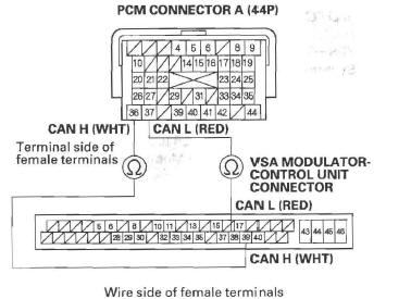
Is there continuity? YES-Go to step 10.
NO-Go to step 14.
10. Update the A/T software in the PCM if it does not have the latest software (see page 14-9), or substitute a known-good PCM.
11. Turn the ignition switch ON (II).
12. Check for DTC(s) in the DTCs/Freeze Data in A/T Mode Menu with the HDS.
Is DTC U0122 indicated? YES-If the PCM was updated, substitute a known-good PCM (see page 14-10), then recheck. If the PCM was substituted, go to step l.
NO-Go to step 13.
13. Monitor the OBD STATUS for U0122 in the DTCs/ Freeze Data in A/T Mode Menu for a pass/fail.
Does the HDS indicate PASSED? YES-If the PCM was updated, troubleshooting is complete. If the PCM was substituted, replace the original PCM (see page 11-219). If any other DTCs were indicated on step 12, go to the indicated DTC's troubleshooting.
NO-If the HDS indicates FAILED, check for poor connections and loose terminals at the VSA modulator-control unit the PCM. If the PCM was updated, substitute a known-good PCM (see page 14-10), then recheck. If the PCM was substituted, go to step 1. If the HDS indicates NOT COMPLETED, keep idling until a result comes on.
14. Check the communication line between the VSA modulator-control unit and the gauge control module with the HDS.
Is there an open or poor connection in the F-CAN line between the V SA modulator-control unit and gauge control module? YES-Repair open in the wires between the VSA modulator-control unit connector and CAN communication lines.
NO-Substitute a known-good VSA modulator-control unit (see page 19-97), then recheck. If the symptom/indication goes away with a known-good VSA modulator-control unit, replace the original VSA modulator-control unit.
DTC U0155: Lost Communication with Gauge Control Module
NOTE: Before you troubleshoot, record all freeze data and any on-board snapshot, and review General Troubleshooting Information.
1. Clear the DTC with the HDS.
2. Turn the ignition switch ON (II).
3. Check whether DTC U0155 is indicated in the DTCs/ Freeze Data in PGM-FI Mode Menu with the HDS.
Is DTC U0155 indicated in the PGM-FI system? YES-Troubleshoot for DTC U0155 in the PGM-FI System.
NO-Go to step 4.
4. Check whether the DTC U0155 is indicated in the DTCs/Freeze Data in A/T Mode Menu with the HDS.
Is DTC U0155 indicated? YES-Go to step 5.
NO-Intermittent failure, the system is OK at this time.
5. Update the A/T software in the PCM if it does not have the latest software (see page 14-9), or substitute a known-good PCM (see page 14-10).
6. Turn the ignition switch ON (II).
7. Check for DTC(s) in the DTCs/Freeze Data in A/T Mode Menu with the HDS.
Is DTC U0155 indicated? YES-If the PCM was updated, substitute a known-good PCM (see page 14-10), then recheck. If the PCM was substituted, go to step 1.
NO-Go to step 8.
8. Monitor the OBO STATUS for U0155 in the DTCs/ Freeze Data in A/T Mode Menu for a pass/fail.
Does the HDS indicate PASSED? YES-If the PCM was updated, troubleshooting is complete. If the PCM was substituted, replace the original PCM (see page 11-219). If any other DTCs were indicated on step 7, go to the indicated DTC's troubleshooting.
NO-If the HDS indicates FAILED, check for poor connections and loose terminals at the gauge control module and the PCM. If the PCM was updated, substitute a known-good PCM (see page 14-10), then recheck. If the PCM was substituted, go to step 1. If the HDS indicates NOT COMPLETED, keep idling until a result comes on.
READ NEXT:
 Road Test
1. Warm up the engine to normal operating temperature (the radiator fan comes
on).
2. Apply the parking brake, and block both rear
wheels. Start the engine, then shift to the D position
while pressi
Pressure Test
Special Tools Required
A/T clutch pressure gauge set
07406-0020400 or 07406-0020401
A/T pressure hose, 2,210 mm 07MAJ-PY4011A
A/T pressure hose adapter 07MAJ-PY40120
1. Make sure the transmissio
Shift Solenoid Valve
Shift Solenoid Valve Test
1. Connect the HDS to the DLC (A).
2. Choose Shift Solenoid A, B, C, D, and E in the
Miscellaneous Test Menu on the HDS.
NOTE: If the HDS does not communicate with the
PCM,
SEE MORE:
Carrying Cargo on the Dual Deck Cargo Shelf
If equipped
On U.S. model is shown
Do not put any items on the dual
deck cargo shelf that could block
your view or be thrown around the
vehicle during a crash.
Do not use the dual deck cargo shelf
if the rear seats are folded down.
Do not exceed the dual deck cargo
shelf load limit o
Tire Pressure Monitoring System (TPMS)
Your vehicle is equipped with a tire
pressure monitoring system (TPMS)
that turns on every time you start the
engine and monitors the pressure in
your tires while driving.
Each tire has its own pressure
sensor (not including the spare tire).
If the air pressure of a tire becomes
signif
